In this writeup I will show you how to configure a Multi-Node Service Graph in Azure using Cloud ACI. We will insert multiple Service devices in-between the communication path of different workloads.
In addition one of the great values of this that you will immediately notice is the horizontal scaling of Firewalls.
Firewall Clustering is a very commonly used feature that is used on Physical Sites for horizontal scaling and for resiliency. Figure below shows typical North/South and East/West Firewall Clustering topology.

However, in cloud architectures Firewall Clustering is generally not supported. So, then the question becomes in Cloud how do you horizontally scale firewalls and still keep state so traffic is not blackholed ?
The answer to the above question is that you insert Load Balancers in front of the Firewall and then configure the Cloud Fabric in such a way with custom routes so, that traffic load balances between firewalls and also the same firewall is used on both sides of the flow so as to keep state.
Could you not do this from the cloud console directly, why use an orchestator like cAPIC to do this ?
The answer is yes, ofcourse you can do it. Now consider the following:
- Manually configuring these custom routes and connectivity options will be very complex and prone to errors.
- As you configure and expand, there are high chances of getting unnecessary configuration sprawl and left over configs that serve no purpose and in fact. could be detremental to the health of the deployment
- Add to this the addition of Network Security Policies that you have to configure manually and keep track of
- Add to this the addition of features like vNET Peering and use of other features
Here is where a single pane of glass ( a SDN controller like cAPIC) comes to the rescue.
- You learn the configuration method once and just apply it.
- No need to worry about configuration sprawl. Your configurations will be optimal and no unnecessary configurations will come in.
- Features like horizontal scaling of Firewall is much easier to do accurately
- All intended security policies will be accurately deployed
- All custom routes will be accurately implemented
- Features like vNET peering for high bandwidth / low latency is just a click of a few buttons and will be done just right
- You don’t need to have multiple cloud providers or even a onPrem ACI Fabric to justify the use of ACI Cloud extension topologies. That is just added benefit. If you did have multiple fabrics in different clouds and onPrem fabric, now you can extend your same policies to the other Sites. However even if you are using just one Cloud Provider this still adds great value
You may wonder, if the configuration is that quick and easy why are my articles so lengthy ?
The reason for this is because I just don’t show you how to configure. I go step by step through elaborate explanations and screenshots and try to show you what happens under the hood, so you can have a good understanding of what’s going on. I also show you methods to test / verify and a lot of testing results. In fact you can use my articles to conduct your Proof Of Concept and show testing results.
If I wrote the article on just how to configure these articles would be very short indeed !
Now, getting back to the topic in hand…
I highly encourage you to go through and even follow the exercises in the previous witeups before jumping into this:
- A Practical Guide to using Azure vNET Peering with Cloud ACI
- Simple Service Graph with Azure Application Gateway & vNET Peering
- Simple Service Graph with Azure Network Load Balancer & vNET Peering
In addition, please go through the following CCO Documentation:
- ACI 5.0(X) Deploying Layer 4 to Layer 7 Services
- Using Multi-Site Orchestrator to Configure L4-L7 Services in Infra Tenant for Cisco Cloud APIC
Doing so will get you very familiar with the basics of implementation method of Service Graphs on cloud with cAPIC and you should be able to go through this article and follow the exercises without having to figure out the basics. I will also not go through every little configuration steps in this writeup. The previous articles already did that so you could now breeze through that sort of thing on your own. That way I can keep this article much more streamlined and to the point without peripheral distractions.
Before we start talking about what we will implement in this exercise and how to do it and test, let’s discuss some theory so it all comes together.
Let’s start off with Routing in Azure Cloud:
There are three types of routes in route table on Azure.
- System routes that are created, updated and owned by Azure.
- Intra-VNET route
- Default route to internet (that is in all route tables created on Azure)
- Peering Routes (if there is a VNET that is peering with another VNET)
- Azure takes care of leaking routes between peered VNETs
- Custom Routes (We call it UDR: User Defined Route for redirection)

The one that you should concentrate on more is UDR (User Defined Routes)
When configuring Service Graphs you often have to configure redirects on the Service Graph device to force the traffic to the desired destination. Under the hood what happens is this creates UDRs in the Azure configuration. You really don’t need to worry about doing these custom routes by hand. cAPIC does all that for you. You can always go to the Azure Console and view them. Also, if you delete Service Graphs, etc, etc, those custom routes are automatically removed thus keeping the Azure side configuration clean.
While going through previous articles I’ve written at unofficialaciguide.com, you will recall that when I create a cloud EPG, I always create a custom tag on that epg and then from the Azure side, I tag my VMs with the appropriate tags, so the endpoints come into the right EPG. As an example. “tier==web” or “tier==app”
If you went and looked at the Azure Console for egress routes for your VRF, you will notice that Azure puts in a appropriate route for the entire CIDR and not for the EPG subnet. For example if my CIDR for app VRF was 10.80.0.0/16 and my APP EPG subnet was 10.80.5.0/24, on the WEB VRF, I would see a Azure egress system route for 10.80.0.0/16 pointing to the Infra default Load Balancer (overlay-1) (if using vNET Peering)
Now when we do a more complex real world Service Graph, let’s say between WEB and APP ( Note: WEB and APP in our example case are on different vNETs, we don’t support redirect in the same vNET) and we use the redirect feature, what you will see is that the UDRs that gets applied will also be on the CIDR level and not on the subnet Level. This could cause a problem. If there are other EPGs in that CIDR, they too will now start getting redirected to the Service Device even though they did not have any contract with Service Graphs associated with them. This will break our intent !
To overcome this, when doing service graphs it’s always best to not use custom tags like “tier==app”. Instead use IP based tag like “ip == 10.80.5.0/24”. Doing so, will guarantee that the UDRs that are configured will be on the subnet level and not on the CIDR level. This way the EPGs with redirect service graphs will go to the correct next hop whereas the other EPGs in that vNET will not be affected.
This is all summarized in the figure below, and you don’t need to memorize it. If you just follow the above logic this becomes very obvious

The next item that I want to discuss are Possible Service Graph Topologies in Azure Cloud.
At this point I would also recommend to open the CCO Documentation on ACI 5.0(X) Deploying Layer 4 to Layer 7 Services and cross reference that as you read along.
Keep in mind that I show the most common topologies here and there may be more that you can cook up. However going through these will give you a good reference

Case 1: Simple Single Node Service Graph: Traffic from Exteral sources need to access your WEB Farm (or other services) In Tenant vNET

Case 2: Simple Single Node Service Graph with Network Load Balancer / Application Load Balancer
(these were the previous 2 writeups for Service Graphs with ALB and NLB)

Case 3: Traffic from Exteral sources need to access your WEB Farm (or other services) In Tenant vNET

Case 4: Traffic from Exteral sources need to access your WEB Farm (or other services) In Tenant vNET
(This time we’ve placed the LB and FW on the HUB vNET (overlay-2))

Case 5: Traffic from lnternal sources need to access Internet. In this example the Internal Source (consumer/client) is on the HUB vNET. Notice that we actually put a Client in the overlay-2 VRF. Overlay-2 VRF can also be used this way. Think about having some sort of Shared services in Overlay-2 as a central point which many other vNETS/Tenants can use.

Case 6: Traffic from lnternal sources need to access Internet. In this example the Internal Source (consumer/client) is on the Consumer vNET

Case 7: Traffic from Consumer vNET to Provider vNET with Service Devices in HUB vNET (overlay-2) and in Provider vNET. I’ve chosen this for the step by step exercise that we will go through in this writeup. This is a very common scenario and will show you many aspects of implementing multi node service graphs and horizontal firewall scaling method

Case 8: NLB-FW Inter-region Spoke-to-Spoke

Below are most common East / West Topologies with ACI Service Graphs for Azure Cloud

I also want to point out to you Topologies that are not supported

- Inter-Site traffic ( for Service Graph purposes) is NOT supported in 5.0.2 release. For example:
- Consumer in AWS provider in Azure.
- On-prem to cloud is not supported.
- Third party load balancer support will come in at Release 5.1

North / South Topology with Redirect on Internet facing NLB.
- Case 7 highlights an example with similar topology that works when consumer is a Cloud EPG (not external EPG)
- Case 4 is the solution for this kind of topology (using SNAT + DNAT) in FW

Now, let’s start doing the actual deployment. Please follow through in your own Azure Fabric so, you get familiar with this.
Step by Step Deployment for Multinode Service Graph with NLB and FW in HUB-vNET (overlay-2) and NLB in Provider vNET

This is building on the previous topology for NLB implemenation.
So, let’s recap where we left off…

We had built a topology where:
- EPG-Web was the consumer and EPG-APP was the provider.
- We configured a contract with Service Graph between EGG-APP and EPG-WEB
- We used vNET Peering for higher bandwidth and lower latency, but we did not host any devices in HUB VNET (overlay-2). So, you could have actually done that exercise without vNET Peering also (using VGW instead)
- The NLB was inserted in the Provider vNET in a subnet of it’s own coming from the vNET CIDR range
- We did ssh testing and netcat testing to show that load balancing was working
- We also investigated from Azure console to see what’s happeing under the hood
- We did tcpdumps on the APP and WEB VMs to verify packet source and destination
- We did packet debugs on the cloud CSRs to verify that packets were going through the CSR (since this was based on a vNET topology)

The logical diagram for that configuration is depicted below in the figure

Now, let’s discuss Where we are going in this writeup / exercise

We will deploy Case 7 that we listed earlier.
- This is spoke to spoke traffic, EPG-WEB being the consumer and EPG-APP being the Provider
- We will install a NLB on the HUB vNET (overlay-2)
- We will install 2 Third Party Firewalls (ASAs). The ASAs will obviously not be clustered (since this is cloud). However we will use the Service Graph Features, UDRs and Azure’s Fabric to do horizontal scaling of the ASAs, so that traffic is load balanced between them while keeping state.
The figure below shows the topology of what we will be doing.
Notice:
- We will insert a NLB and 2 ASAs in HUB vNET (overlay-2)
- Traffic from WEB-EPG to APP-EPG will now no longer go through the default infra NLB and CSRs. They will instead go through the newly installed NLB and firewalls in HUB vNET overlay-2

The Logical Diagram of this is shown below

Before we start:
Let’s first get rid of the following old configurations from the NLB Install:
- From MSO, disassociate Service Graph from contract
- From MSO: delete the Service Graph
- From cAPIC: Delete the NLB
( Please review NLB writeup if needed for procedure on this)
Once you do that, please ensure that WEB-VM can still reach the APP-VM. Since the contract is still there, that should work

Recall that in the previous examples we had used Cloud EPG tags as “tier==web” and “tier==app”. That was fine during that case, because we were not doing any redirects in the service devices in those examples. However for this example we will have to configure redirects on the HUB vNET (overlay-2) NLB. That changes the equation. Let’s change the cloud EPG selectors and make them IP based instead of label based. You don’t need to change tags on the VM side. They can still have those tags, it does not harm anything.
( Note: EPG Selectors for cloud EPGs can be configured from either the Main Template/Cloud Properties/Add Selector, or from the Site Local Template. Site Local Template has more options for e.g. IP match. It’s best to be consistent and do it from Site Local Template only)

After changing please do a ping test to verify that the WEB and APP VMs have come back to the correct EPGs.
First do a ping test from WEB to APP


Since we will be installing Service Devices in HUB vNET (overlay-2), let’s review our initial setup for the fabric. This was shown in details in the writeup for cAPIC 5.0.2 install
If you recall, we had used RFC 6598 address range 10.64.0.0/10 range for configuring overlay-2 CIDR and subnets
| Primary CIDR | 100.64.0.0/16 |
| loadbalancer | 100.64.5.0/24 |
| firewall-untrust | 100.64.6.0/24 |
| firewall-trust | 100.64.7.0/24 |
| HubVMSubnet1 | 100.64.8.0/24 |
| service-mgmt | 100.64.254.0/24 |

Now, let’s go ahead and create the ASAs (3rd party firewalls) in Azure and place them on HUB vNET overlay-2

Since these are 3rd party firewalls, we obviously have to configure them manually. To do so we need to SSH into them or use a UI of some sort (Cisco Security Manger for example for the ASA). So, we need to have the mgmt interface of the ASA exposed to the public network (with required security), so we can ssh to it.
Overlay-2 HUB vNET has a default externalEPG called “all-internet“. We will build a EPG, place the FW mgmt interface on that EPG (with the help of Cloud Selectors on that EPG). Then we will use a contract between the fw-mgmt EPG and the all-internet externalEPG to accomplish this.

Let’s first build the fw-mgmt EPG. This is not a normal Tenant object but rather a infrastructure object. For that reason we cannot build this through MSO. We need to build this directly through cAPIC

configure the FW-mgmt epg as shown in the figure below

Put in a Cloud Selector for that EPG. This can be label based if you want. There are no Service Graphs associated with this mgmt NIC

Now Create the Contract that we will use between this Fw-mgmt EPG and all-internet EPG

Fill in the fields for the contract as shown below

Now we have to add the contract between the fw-mgmt cloud EPg and all-internet extEPg. To do this on cAPIC UI click on intent icon and then click EPG communications

Now choose the contract that you made earlier, and add both the cloud EPG “FW-mgmt” and the externalEPG “all-internet” as both provider and consumer.

Before we start deploying the ASA, we need to create 2 public IPs that we will use for our ASA mgmt interface (one for each ASA). Please go ahead and make these. I named mine “sm-asa-eastusasav1-pip” and “sm-asa-eastusasav2-pip”


Now we have to install the 3rd party unmanaged Firewall device to Azure. You can do this in different ways.
The most common way would be:
- In Azure console, go to market place and look for the Firewall you are interested in and subscribe to it and then deploy it. However you will need to fix the parameters before you deploy to confirm to overlay-2 subnets you have defined.
- Deploy from a pre-made template just for this purpose. If you did it this way you can make some minimum parameter changes in the json template file and then deploy.
If you use method 2, then you will first need to do a google search for the ARM template for your interested firewall. Then get the json file for the template. Then you can modify that json file in a text editor (like sublime or atom) before deploying. You can also edit the parameters while deploying.
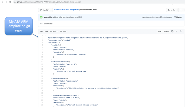
For the purpose of this exercise you can get the ASA template from my git repository. Just click here for the ARM ASA template for cAPIC.
In that same repo, I also have a FTD template and a Palo Alto Networks Firewall template. Click here for those.
Below Figure shows you the ASA template in my git repo.
To deploy the template, go to your Azure Infra Subscription (remember this is the Infra vNET (HUB vNET overlay-2) where we will be deploying the ASA firewalls.
Then in the searchbar type in “template” and click on Templates as shown below

Next, click on “Add” to add the template.

Give the template a name and description and then click “OK”

When the Arm Template opens up it will have some preliminary json code in it.
- Just delete all of that generic code.
- Then paste in the code for the ARM template for ASA from my git repo.
Note: if you have been following my exercise exactly with the same subnets in overlay-2 and same name for the subnets, then you don’t have to make much changes. If you did differently then you will need to make few more changes in the json file but it’s not that much. You can first make the changes in an editor of your choice before pasting it in, or you can just paste in the code from my repo and edit on the Azure Console itself during deployment.

On the next page, just click Add

Refresh the screen for the new Template to show up

Now Click Deploy Template

The following form will show up now from the template values. Please look at the figure below and change your parameters accordingly.

More values of importance shown below (as you scroll down your template deployment form). When done Click Agree and Purchase

The ARM Template will now start running. Click on the Bell Icon to see the details. As shown in the figure below you can watch for errors if any happen because of a wrong parameter you put in. Then you can view the details of that. If there was a problem, delete the deployment of the template. Deploy again after fixing the parameters that caused you problems.

In case it failed due to some error like bad parameter, you should also go into the cAPIC resource group, and clean up the objects that were deployed due to the template. That way you don’t have junk in that resource group. Also, if you already have something while trying to deploy the template again, it won’t like it.

Once the deployment is finished, go to the ASA VM click on NIC0/Network Interface. This is the mgmt interface of the ASA.

Now add the tag that you used in the cloud EPG for FW-mgmt. In my case the value I added was “tag==fw-mgmt”. This should make the management NIC of the ASA go into that EPG.

Now Go to the other Interfaces of that ASA firewall and put the tag values in as shown in the figure below

Now go ahead and get the public IP of the ASA FW mgmt interface and you should be able to ssh right into it.

You can see below the ASA mgmt interface IP is what was defined in the template. It obtained that from dhcp.

Now go ahead and do the basic configuration for ASA1. the left side of the configuration will already be there. All you need to do is the right side of the configuration,

You are all done deploying and configuring the ASA firewall. Let’s go ahead and bring up the 2nd firewall

The process is exactly the same. However while running the ARM template please make sure that you choose the correct parameters. Don’t duplicate IP,s name, etc, etc with the 1st ASA deployment template.

Moving down the template screen…

Deployment done below

Now for the 2nd ASA firewall tag the interfaces just like you did for the 1st ASA firewall

Do the basic configuration for ASA2

Firewall device has been setup from Azure console to be used and firewall basic config has been completed. Next we need to add the firewall devices in from cAPIC.
Note: You don’t need to add them both in. You just add one in, since they will be horizontally scaled. The selector values will get both firewall interfaces, since they both have the same selector values

Go to cAPIC UI Application Management/Services, click on Devices, then Actions / Create Devices

Create the 3rd party firewall as shown in the figure below.

Once you create Add Interfaces, put in your first interface and the tag values as shown in the figure below

Add in the other interfaces, trust and unused also as shown below

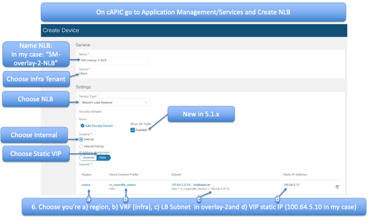
Next you need to create the NLB device for overlay-2.

You have already created NLB device in previous writeup. The procedure is exactly the same except that you will choose the overlay-2 VRF and the subnet you choose should be the one you defined in overlay-2 as the load-balancer subnet
We have one more device to create and that is the NLB device in the Provider vNET (APP vNET in our example case). We’ve done this exact thing before in the NLB writeup.

Follow the figure below to fill in the fields

The last step that’s left is to Create the Service Graph and add it to the EW-C1 Contract

Create the Service Graph Chain as shown in the figure below

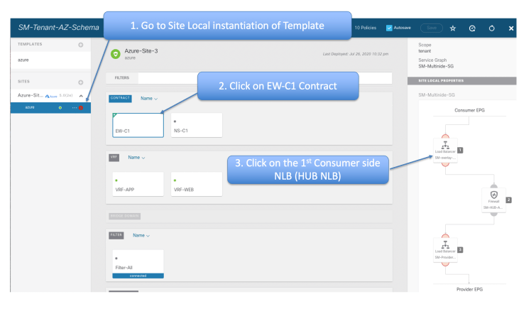
Now Go to the Site Local Instantiation of the template, Click the 1st device ( the NLB) and then associate it with the HUB NLB

Choose Redirect for both Consumer and Provider connectors

After clicking next (above) it will take you to the next device in the service graph chain which is the Firewall. Associate that with the HUB ASAs.

Choose the G00-untrust interface for both Consumer and Provider, since this is 1-Arm deployment. Make sure to choose None for Provider connector type.

Hit Next and it will take you to the next device in the Service Graph Chain. This happens to be the Provider Side NLB. Choose it and click done.

Now from the Main Template add the Service Graph to the EW-C1 contract

The last step of this is to create the listeners and rules in the NLBs. To do this go back to the Site Local instantiation of the template, and click on EW-C1 and then the 1st device, which is the HUB NLB
Create your Listener for the HUB NLB as shown in the figure below

Click Next and you will be taken to the next device in the chain, the ASA. There is nothing to configure there because it is a unmaged Firewall.

Now you land up to the last device in the chain. The Provider side NLB

Configure the Listener on the Provider Side NLB as shown in the figure below

Next, Click Done and make sure to go to main Template and click Deploy to Sites

Configuration is Done !
Time for testing

Let’s do our ssh test first

From the Figure below, you can see that ssh sessions are getting load balanced. They end up in different APP VMs every time.

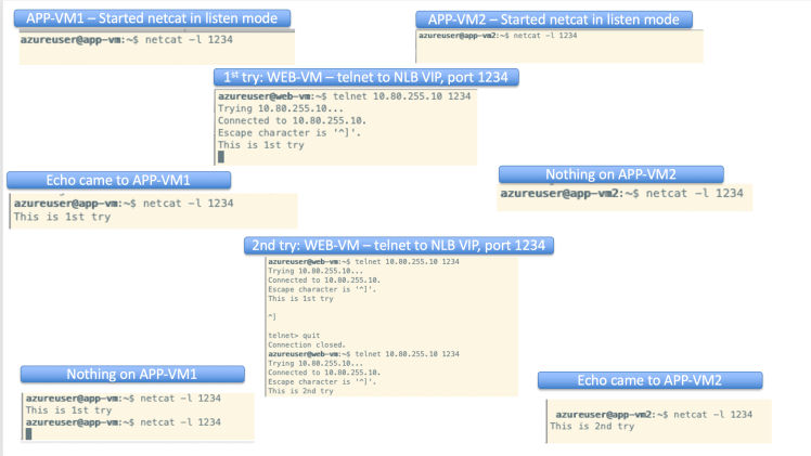
Now, let’s do our netcat test using port tcp 1234

Below is the procedure to start up netcat listener and send traffic to the netcat listener

Results of netcat clearly show that load balancing to destination is working as intended
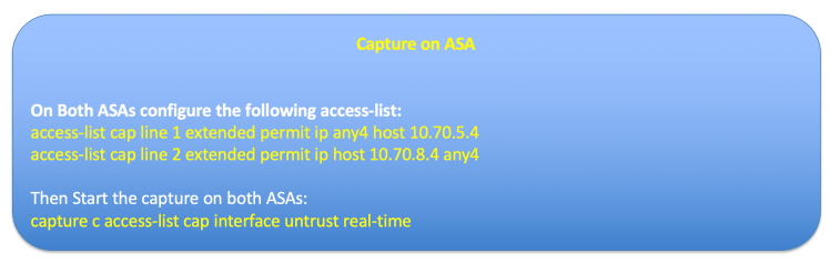
Now let’s do some capture on the ASAs to see if the ASAs are load balancing the traffic
on the 1st SSH from Consumer (WEB-VM) to the Provider NLB we see that the packets are using ASA2

We try our ssh again and this time we notice that the packets are going through ASA1

Conclusion: Our Horizontal Scaling of ASA is working. Not being able to cluster the firewall on the Cloud has not been a problem for us ! We are load balancing over the ASAs and keeping the state of flows on individual ASAs.
Before ending this writeup, let’s look quickly from Azure console to see the Azure routes including UDRs.

for Tenant Provider vNET we see the System Route and the UDR (User Defined Route) as you can see below.

Similarly we see the System Route and UDRs for the APP vNET

We can also view the routes on the Untrust interface from the Azure Fabric Level.
To do this go to one of the HUB ASAs. and click on the NIC1 ( the untrust interfaces that we are using). This is illustrated in the figure below.

Now, click on Effective Routes and you will see the System Routes on the Untrust Interface subnet on the Azure Fabric level

In this topology the traffic flow from Consumer to Provider is illustrated below

The return traffic from Provider to Consumer is illustrated below

References:
- Cisco Cloud ACI on AWS White Paper
- Cisco Cloud ACI on Microsoft Azure White Paper
- Internet Service for Cisco Cloud APIC Workloads: (how to create untrusted user)
- Cisco Cloud APIC for AWS Installation Guide, Release 5.0(x)
- Shared On-Premises L3Out for Cisco Cloud APIC Workloads
- Cloud APIC Install Guide-Azure
- Cisco Cloud on Azure White Paper
- Cloud APIC Install / Upgrade & Configure Guide
- ACI 5.0(X) Deploying Layer 4 to Layer 7 Services
- Using Multi-Site Orchestrator to Configure L4-L7 Services in Infra Tenant for Cisco Cloud APIC
- Azure documentation – Load Balancer health probes