In this blog post, I will discuss with a practical approach on how to utilize Azure Cloud’s vNET Peering feature which is now supported with Cisco Cloud ACI from release from cAPIC release 5.0.2e
So, What is vNET Peering in Azure and why should you use it ?
From Microsoft Azure Blogs, I found a very nice comprehensive discussion on this.
VNet Peering provides a low latency, high bandwidth connection useful in scenarios such as cross-region data replication and database failover scenarios. Since traffic is completely private and remains on the Microsoft backbone, customers with strict data policies prefer to use VNet Peering as public internet is not involved. Since there is no gateway in the path, there are no extra hops, ensuring low latency connections.
VPN Gateways provide a limited bandwidth connection and is useful in scenarios where encryption is needed, but bandwidth restrictions are tolerable. In these scenarios, customers are also not as latency-sensitive

If you have read the previous article on AWS Transit Gateway usage with Cloud ACI, this will seem very similar to you. The idea is very similar, though in the Cloud ACI implementation there are a few differences due to the underlying cloud architecture differences. I’ll point these out as I go.
Azure vNET Peering is:
- Non Transitive: meaning if vNET A is peered to vNET B and vNET B is peered to vNET C, that does not imply that vNET A can talk to vNET C using vNET B as a transit vNET (by default). That’s why Cisco uses a hub and spoke model for vNET Peering. Else, it would become too much of a mes(s/h).
- vNET Peering is based on static routes. There is no concept of VRF. This implies that you cannot have overlapping subnets for vNETs that use vNET Peering. Ofcourse you can use VGW and vNET Peering at the same time (just like you can use TGW and VGW in AWS at the same time)
- Both vNET Peering in Azure and TGW in AWS have capability of using User Defined Rotues also known as UDRs
Inter Region Peering:
- In Azure there are 2 kinds of vNET peering:
- Local Peering – Peering in same region
- Global Peering – Peering between regions
- if a prefix is reachable by both Local vNET peering and Global vNET peering, by default, Local vNET peering has precedence (since it’s lower cost)
- In AWS TGW, each VPC can have TGW VPC attachment to TGW Service (also known as TGW acceptor). TGW Gateways can peer to each other across regions.
Now that we’ve discussed vNET Peering and what it is, let’s take a practical approach and use Azure vNET Peering feature with Cisco Cloud APIC (5.0.2e and above)
As we build our ACI Fabric Tenant topology and utilize Azure’s vNET peering and investigate how this works. Let’s start building the following topology. To start off with, let’s just first build the shaded part of the figure below which is the Tenant and the VRFs. I will only point out newer things that need to be done for using vNET peering and will not show every little step of clicking and accepting. By now if you have followed the other writeups you will be very comfortable on using the MSO to build ACI objects in the cloud. ACI objects are built the same way regardless of the underlying cloud provider or physical Fabric (with some minor differences).

In the figure above you will notice that VRF-WEB is in the West US region, whereas VRF-APP is in the East-US region. The East US region also happens to be the home region for ACI Cloud. The home region in ACI Cloud is where cAPIC is deployed. The home region always has cloud CSRs deployed. Other Regions for that particular fabric (ACI Site) can also have CSRs if you wish, but they are not considered home region.
If you recall from the 5.0.2 cAPIC for Azure Install article, for this particular fabric, my home region was East US and I had 2 more regions, Central US and West US where I chose not to deploy any cloud CSRs. So, my only Cloud CSRs are in my East US home region.

In the Cisco Cloud ACI Azure Implementation using vNET peering, we use a hub and spoke model.
The HUB is always the Infra vNET that has CSRs (regardless of it being a home region or not). In other words if you don’t have any CSRs defined in a region that region cannot be the HUB for vNET Peering purposes.
Now looking at my setup, since my cloud CSRs are in the East US region, that can be a HUB for vNET peering. My other regions don’t have CSRs so, they cannot be HUBs.
Since I have a tenant vNET in region WestUS and I’ve decided to use vNET Peering for that vNET, it has to peer with the EAST US HUB region for vNET Peering.
Also, please pay attention to the Azure Native NLB (Network Load Balancer) in the HUB vNET. This NLB load balances the traffic to the 2 CSRs. We’ll discuss more about this a bit later.
The diagram below should make this clear.

Contrast this to the AWS TGW setup that we did before. You will immediately notice that for TGW purposes, we don’t care if the other region has CSRs or not. Every Tenant VPC will have a TGW Attachment with a TGW in it’s own region and the HUB TGWs peer to each other. The figure below shows that example.

Below is a diagram showing ACI Cloud Azure Fabric with more than 1 region having CSRs.
Here you will notice the following:
- The infra VNets are used as the Hub
- CSRs in the Hub VNet act as the NVAs for Spoke to Spoke routing
- NLB is placed in front of the CSRs to perform load-balancing and failover
- All Spokes VNets are peered with all Hub VNets(across regions)
- UDR (User Defined Routes) in the Spokes VNets are redirecting the traffic to the CSR NLB for traffic destined to other spokes/sites

Going back to our example setup:
- In This Case, I will create the ACI Tenant on a totally separate Azure Subscription (in same directory as Infra Tenant). ( current release does not support vNET Peering for Azure subscription on different Azure directory subscription)
- Let’s make sure that before we start we give the proper permissions to the Azure Tenant Subscription.
- There are 2 Roles we need to define:
- On Tenant subscription define Contributor Role for cAPIC of Infra account (please see the article on — Adding Tursted/Untrusted Accounts in unofficial guide)
- On Tenant subscription define Network Contributor Role for cAPIC of Infra account

After you configure your Schema/template in the MSO and map it to your Azure Tenant and create the VRFs, you will go to the Site Local implementation of your template and configure the details for the VRFs. Here you will choose the region and the CIDRs/subnets. When doing vNET peering only for the VRF, you don’t need to define a subnet for VGW gateway.

Make sure to check vNET peering and the HUB Network which is called “Default”

Do the same for the APP VRF

Enable vNET peering also for APP VRF

Before we configure the rest of the ACI Teant, i.e. EPGs, Contracts, etc, etc, let’s see what happened till now.
Go to the cAPIC Azure UI and click on Application Management / Cloud Context Profile. Then Double click one or your Tenant VRFs

Look for the Health/Faults and if you see any problems look at Event Analysis for details. Click on Cloud Resources and investigate the options.

On cAPIC go to Application Management / VRFs and double click on one of the user VRFs.

Like before check for Health/Faults and click on Event Analysis if you see any problems. Click on Cloud Resources to investigate

Now, click on Cloud Resources / Virtual Networks and then double click on one of the tenant VRFs that you created

Next, click on Cloud Resources

In the next screen click on Virtual Network Peers

Here you will see the vNET Peers. On each of the tenant defined VRFs you will see 2 vNET Peers. This is because the vNET peering consists of 2 unidirectional peers. One going to HUB vNET and the other coming in from HUB vNET

If you wnet to Infra vNET overlay-1, you will see 4 vNET peers. in/out to vNET APP and in/out to vNET WEB

You could also check the vNET peering from the Azure Console. Go to Azure console UI and then go to overlay-1 vNET and look at Peerings. Note that from Azure UI, it will show you 2 vNET peers only. The way Azure UI shows it is that if the vNET peering has both in and out (meaning configure from overlay-1 side to vNET APP and then go to vNET APP and configure vNET Peering to overlay-1, then the vNET peering is considered completed and it will say connected for Peering State. If you only do it from one side, it will say initializing for Peering State.

Similarly, looking in Azure UI from vNET App will show one connected Peer to infra vNET overlay-1

At this point let’s go ahead and configure the rest of the ACI objects for that tenant. The un-shaded parts from the figure below

On azure console search in the search bar for vrf. Choose one of your Tenant vrfs route table. Let’s say web_egress

Click on Routes. You will see that the route to 10.80.0.0/16 (the APP VRF) is pointing to 10.33.1.36. Also, if you click on Subnets you will see that the subnet for this vrf (WEB VRF) is 10.70.5.0/24

You will see a similar kind of reslut for APP VRF_egress

Now on Azure UI, search for load balancer

Choose your hub NLB (Network Load Balancer )

Click on Frontend IP configuration. You will see that that 10.33.1.36 IP that we saw before is actually the Front End IP for the NLB

Now for that NLB, click the Backend Pools and you will see that the backend pools configured for that NLB happens to be the Gig 2 interfaces of your Azure Cloud CSRs. ssh in to your cloud CSRs and verify.

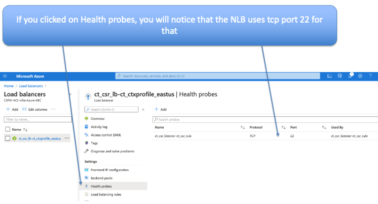
If you click on Health probes, you will notice that the NLB is using tcp port 22 for health probes
click on NLB / Monitoring / Metrics and choose the Health Probe Status Metric. From here you can see the staus of the Health Probes recieviced. If it is at 100% then all is good.

also check for the Data Plane Availabilabilty Metric

So, now that we have confirmed that everything is looking good, let’s bring up a workload (VM) for WEB and one for APP. Let’s first start with the APP VM.


Please make sure to put the tag key:value pair as you had defined in your MSO for EPG Selector policy for APP EPG

Once VM is created, go to the VM and look at Networking. Make a note of the Private IP (10.80.5.4) in my case. Also observe that the security group is the default security grou ending in nsg

Note: In cAPIC release 5.0.x, the NSG (Network Security Group) used to attach to the network Interface. From 5.1.x, the NSG attaches to the subnet instead. This affords the benefit of having more comprehensive security policies with fewer entries. Please see diagram below:

very soon the security group name will change and you will see new Inbound security group rules come in (based on the contracts you defined from MSO)

You can see this endpoint from cAPIC also by going to EPG/Endpoints

Repeat the same process to bring up a WEB-VM in the West Region. Make sure to match the tag to what you configured as EPG Selector on MSO for EGP-WEB (in my case tier==web)
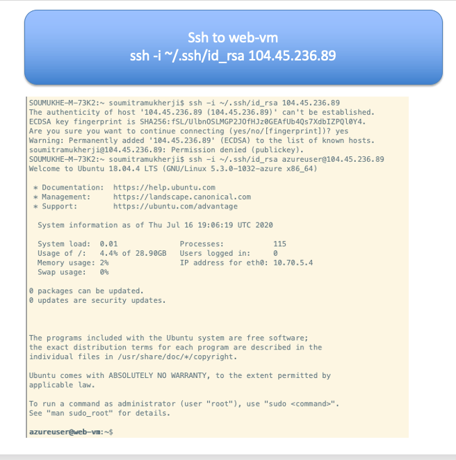
Once it’s ready you should be able to ssh in to WEB-VM. Get the Public IP of the VM from Azure Console and looking at networking for WEB-VM

ssh to web-vm
From the web VM ping the APP VM Private IP

While the ping is running, let’s do some debug catpures from the cloud CSRs.
The commands on the CSRs to be used are as follows:
- debug platform packet-trace packet 128
- debug platform condition ipv4 10.70.5.4/32 both
- debug platform condition start
- debug platform packet-trace packet 128
To View:
- show platform packet-trace statistics
- show platform packet-trace summary
To Stop:
- debug platform condition stop
Other Useful Commands:
- show platform packet-trace code # Show packet-trace drop, inject or punt codes
- show platform packet-trace configuration #Show packet-trace debug configuration
- show platform packet-trace packet #Per packet details for traced packets
- show platform packet-trace statistics #Statistics for packets traced and packet disposition
- show platform packet-trace summary #Per packet summary information for traced packets
- clear platform packet-trace configuration
- clear platform packet-trace statistics

From the debug you will observe that the ping packets are actually going through the cloud CSRs.

Currently CSR1 is not the datapath for these ping packets. Some other source/destination hash will fall on this.

Analysing this, we will see that the packets are going from VRF-APP, East US region to the HUB NLB to CSR-0 through the vNET Peering and then through the vNET Peering to VRF-WEB, West US region and then to WEB VM

Contrast this to what we saw in the TGW writeup. You will notice that from VPC to VPC in AWS, the data path does not hit the CSRs. Also, there are no NLBs there either in infra.

Let’s also take a look at the Cloud CSR configurations that was pushed from cAPIC when we built our Tenant.

You will notice that there are quite a bit of configurations that got pushed down from cAPIC on to the cloud CSRs. If you look at this, you will appreciate that this is rather complex configuration and would be hard to configure on a large scale by hand. Cisco Cloud ACI is doing all this for you without your involvement.
- BDIs got pushed for each of our VRFs.
- Gig2 on the CSR got programmed with a route-map
- The route-map matches the proper prefixes for each user VRF and inserts them in the proper BDI (proper user VRFs)
- Based on the Contracts configured the proper Static routes are configured and then redistributed into the proper VRF


Network Watcher is another nice utility in Azure CLI that can be pretty handy


References:
- Cisco Cloud ACI on AWS White Paper
- Cisco Cloud ACI on Microsoft Azure White Paper
- Internet Service for Cisco Cloud APIC Workloads: (how to create untrusted user)
- Cisco Cloud APIC for AWS Installation Guide, Release 5.0(x)
- Shared On-Premises L3Out for Cisco Cloud APIC Workloads
- Cloud APIC Install Guide-Azure
- Cisco Cloud on Azure White Paper
- Cloud APIC Install / Upgrade & Configure Guide