In this blog post, I will discuss with a practical approach on how to utilize AWS Transit Gateway Functionality for Cisco Cloud ACI.
So, What is Transit Gateway (TGW) in AWS and why should you use it ?
If you search AWS documentation on TGW, you will see the below:

Next thing to keep in mind is TGW Pricing.
From Amazon’s documentation, you will find the following:

Let’s summarize the benefits of using Transit Gateway in AWS
- AWS Transit Gateway (TGW) is a transit hub to connect AWS VPCs and to connect AWS VPCs with the on-prem sites.
- Simplified multi-VPC connectivity
- A hub-spoke topology in which TGW is the hub and VPCs the spokes. Prior to TGW, multi-VPCs connectivity required either full-mesh VPC peering or a transit VPC design with VPN overlay. Both have high complexity.
- Higher bandwidth for inter-VPC connectivity.
- It can go up to 50 Gbps, compared to performance in transit VPC design — up to 1.25 Gbps per VPN tunnels.

Let’s look at this from an ACI prospective.
- Prior to ACI release 5.0, Cloud ACI use the transit VPC with VPN overlay design to provision multi-VPC connectivity. The infra VPC is the transit hub VPC and the user VPCs are the spoke VPCs. VPN tunnels run between VGWs in user VPCs and the CSR1kv routers in the infra VPC. Transit VPC designs are complex and have performance limitation — Bandwidth is limited to 1.25 Gbps per VPC tunnel, and VGW does not support ECMP.
- From release 5.0 onward (with MSO 3.0(i1) and higher, Cloud ACI supports AWS TGW for multi-VPC connectivity. It provides simplicity and higher bandwidth. TGW is the transit hub and the infra VPC and user VPCs are the spokes that attach to the hub. TGW provides routing between the VPCs.
- Cloud ACI uses AWS TGW to provision cloud native network infrastructure for the following scenarios:
- Regional multi-VPC connectivity
- Inter-region network connectivity
- AWS cloud site to On-premise site/ other cloud site connectivity
Note: Incidentally, a similar functionality will be supported for Cloud ACI for Azure Clouds (using vNET Peering), in the next cAPIC release.
Let’s take the case of the options that we had before release 5.0 of cAPIC.
In the diagram below I depict a AWS / ACI Cloud Fabric.
- The Infra setup for this particular fabric spans 2 AWS regions, West and East. (this means that you can build your tenants in those 2 regions). This is a choice you can configure from the initial setup screen or modify and add more regions later
- In this setup I have chosen to spin up vCSRs in the West Region (where cAPIC resides – this is a must).
- In addition, I have also chosen to spin up vCSRs in the East Region for the Infra Tenant.
Results of this approach:
- Full Mesh of IPsec tunnels will be created from each VGW (Virtual Gateway) to each vCSR.
- Each vCSR will also establish IPSec tunnels with CSRs of other regions (the bgp evpn peering for control plane and the vxlan tunnels for data plane will be inside the IPsec tunnels)
- The tunnels to do all this connectivity actually goes through the Public Internet (On CSRs, Gig 2 is used for the source interface of VGW tunnels and G3 is used for the source interface of tunnels to other CSRs — recall that both G2 and G3 needs AWS elastic IPs for this purpose)

A more common approach is to not spin up the vCSR in the other regions (East Region in my case). As you can see if you did it this way, you have fewer IPSec tunnels, but the idea is similar.

Key points to remember:
- Using TGW instead of using VGW will make your tunnels go through the AWS internal network (hence the better bandwidth).
- TGW can be used in addition to VGW, which is actually required at times as we will illustrate later in this blog
- Unlike VGW peering which uses bgp, TGW forwards packets based on static routes. So, if you have both TGW and VGW, in most cases TGW will be preferred because of static having lower AD.
- When enabling TGW from the initial setup, you don’t need to spin up multiple TGWs. The same TGW can be used by infra for all your AWS tenants in those regions
Now, that we got the theory basics covered, let’s approach this from a practical viewpoint. I believe this is the best way to be able to understand how TGW can be integrated with ACI Cloud Fabric.
I recommend that you follow through this exercise in your own Fabric, so you can actually get a good sense of it.
I’m also assuming that you have gone through my other previous blogs and followed through in your own setup. For that reason, I will not go through every small step of clicking buttons but will convey the idea to you.
Let’s build a Tenant depicted in the diagram below.
- We have 2 Sites, Site2 is AWS Site3 is Azure
- We stretch a VRF across the Sites
- In the AWS Site2 we use 2 Regions, us-east-1 and us-west1
- The cAPIC happens to reside in us-east-1
- We stretch our WEB-EPG across both Sites (and regions in AWS site2)
- I spin up EC2s, one in each region in AWS and a VM in Azure eastus region
- Both AWS and Azure have been configured with External EPGs and contracts to enable Internet Access so, I can SSH to the EC2/VMs
- Before you start building this Tenant, we need to first make sure that we enable both East and West Regions in AWS and enable TGW HUB from cAPIC initial setup

Before we start building the Tenant, let’s go to the cAPIC initial configuration to enable us-west-1 region and also install the HUB (TGW).
To do, this go to the cAPIC for AWS and click the buttons shown below to bring up the initial config screen
I’m assuming that you don’t already have your TGW setup in the initial APIC setup. If you already have that setup, just review it, don’t create a new TGW (no need to)

The Initial Configuration screen shows up. Click on “Review First Time Setup”

Click on “Edit Configuration” for “Region Management”

On the next screen do the following:
- Enable TGW
- Enable TGW Stats for the cAPIC Region ( US-East) in my case
- Enable Region for US West (or a region of your choice). Note all regions in AWS may not support TGW.
- Enable TGW Stats for the new Region (US-West, in my case).

Make sure to configure a HUB Network and name it something. I named mine TGW. Also, you can configure a BGP AS# for this. If you choose not to, it will configure a default AS of 64512 (need to verify this default AS #)

Now, go ahead and build the Tenant based on the logical Tenant diagram shown above in Figure 6.
One important thing to keep in mind is this:
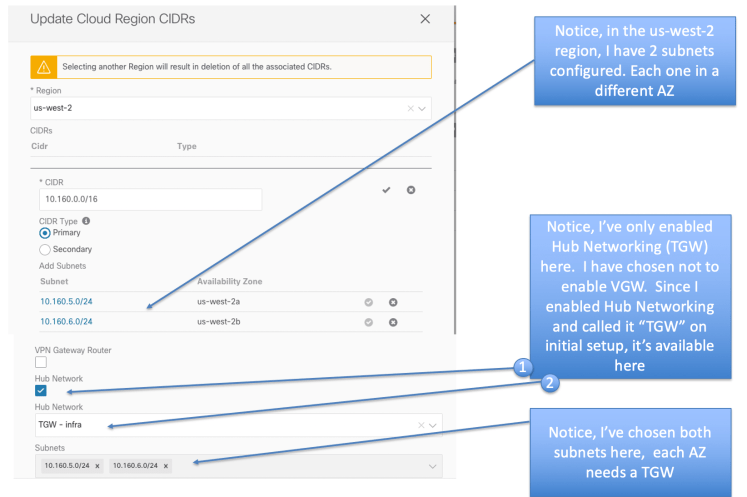
When attaching a VPC to a transit gateway, you must specify one subnet from each Availability Zone to be used by the transit gateway to route traffic. It will deploy an Elastic Network Interface (ENI) (don’t confuse ENI with Elastic IP, they are not the same) to each Availability Zone in the VPC.

Notice Below in Site Local Template for AWS VRF, I’ve chosen both us-east-1 (using CIDR 10.140.0.0/16) and us-west-2 region (using 10.160.0.0/16). Recall we enabled those 2 regions, in the initial APIC setup, so those are our choices here.

In us-east region, I have 2 AZs that I configured us-east-1a and us-east-1b. I’ve chosen “HUB Networking” (analogous to TGW in ACI speak). I’ve chosen not to enable VGW (to prove a point later during this exercise).

I’ve done the same thing for the us-west Region
If you recall when using VGW, the VPC configuration in AWS is not pushed. It’s only pushed after you configure your EPG and deploy to site. When using TGW you will notice that your VPC configuration is immediately pushed to AWS. Go the the AWS console and verify this.

On the AWS console check out the Transit Gateway section under VPC menu. You will notice that both Infra Account and Tenant Accounts now have Transit Gateways pushed to them. There is a 1:1 match on the Transit Gateway IDs on Infra Account, and Tenant account. Make sure to check both the Regions of your Tenant account and Infra Account.

Also, if you click on “Transit Gateway Attachments” you will see the attachments there. (make sure to check both Infra and Tenant Account in both regions).

Also, on AWS console for both Tenant Account and Infra Account, check on “Resource Access Manager”, (fondly known as RAM). You will notice that the Tenant Account will show TGW resources as “Shared To Me”, whereas the Infra account will show resources as “Shared by Me”

Let’s analyze:
This is what happened when you did the above steps.
- User added VPC to GatewayRouterP ( don’t worry about the object name at this point.)
- cAPIC created TGW on Infra Tenant and shared to User Tenant. (TGW on Infra can share to multiple user Tenants)
- On another point in this setup the TGW subnet and the EC2 workload subnet are the same. However, it is best practice to keep them separate.

Notice that on both Infra and Tenant account Elastic Network Interfaces (ENIs) have been spun up (check from AWS console under EC2 menu)

At this point, lets recap how the 4 Gig Interfaces in the vCSRs used

Notice that Gig 3 is used for the IPsec tunnels to the other CSRs in other sites

We’ve discussed before that Gig2 is used for the TGW/VGW peering. After you did the above configuration, you will notice something different about Gig2 configuration (look at Figure 24). You will see that a policy route-map has been applied there.
The reason for this is that TGW forwarding is based on static routes (unlike VGW that uses bgp l2vpn evpn). So, if it’s based on Static Route forwarding, how do you keep the VRF information.
This is done by the policy route-map. In this case you will see that policy route map is matching on my east-region prefix of 10.140.0.0/16 and making sure to put that on the correct VRF (my Tenant VRF).
What about 10.160.0.0/16 for my west-region prefix ? Why is it not there ?
More on that in a bit later.

In the Infra AWS account you will notice that the TGW routes are pointed to the Tenant Accouns VPC subnets. Also Notice that some of them say “Resource Type of VPC” and some of them say “Resource Type of Peer”

In the Teanant Account for us-east-1a AZ, Notice how VPC subnets have a TGW route and also the default gateway for IGW. The IGW route is becuase we configured External EPG for Internet connectivity

Same situation for Tenant Account us-east-2a AZ

Now Let’s go to the console of AWS and Azure and make a list of what the Public IPs and Private IPs are for our EC2/VM instances

Let’s ssh to the EC2 instance in us-east-1a AZ ( the AZ that also has the cAPICs and vCSRs) and try to ping the VMs ( the Private IPs) of the other AWS region and also the private IP of the Azure Region. Recall everything is in the same EPG, so we expect this to work.

Let’s try to do the same sort of test from ssh’ing in to the EC2 instance in the us-west-2a AZ ( the region that has no vCSRs). Again, they are all in the same EPG, so we expect it to work. However you will notice that we can ping the EC2 in the other region from there, but not the Azure VM !!!

Let’s try to figure out what’s going on. To start off let’s ssh to one of the Azure vCSRs and check what’s going on there. You will notice from Figure 31 that we see that a VRF has been created there that corresponds to my Tenant VRF

From “show bgp l2vpn evpn” (figure 32) we can clearly see that the prefix 10.160.0.0/16 from us-west-2a is missing there !

Further confiriming the route table in my user VRF in the vCSR, I see the same thing that 10.160.0.0/16 from AWS us-west-2a is missing !

Let’s now go to one of the AWS vCSRs and see what’s going on there (figure 34). We see our user VRF there.

You will see that 10.160.0.0/16 from AWS us-sest-2a is missing there also (we had previously noticed that too). (figure 35)

Let’s go to AWS console and see if we can figure out the problem as to why we don’t see the us-west-2a prefix of 10.160.0.0/16 on the vCSR of AWS.
If you pay close attention, you will notice from AWS console for Infra Account when looking at Transit Gateway Attachemts, that some of them are VPC attachments while others are Peering Attachments. (figure 36)

However, when you look from the AWS console for Tenant Account, you will only see VPC Attachments for TGW, you will not see any Peering Attachements for TGW (figure 37) ( 7/10/2020 — Just realized that the screenshot is a duplicate of Figure 36, I will have to recreate this scenario and put the correct screenshot for Figure 37)

Let’s analyze again from our findings. What we notice is that Tenant VPCs are attached to their local TGW in infra and there is peering between TGWs. Obviously when you ping from one EC2 in a region to another EC2 in another region, the packet never has to go to CSRs. So, it works. (figure 38)

If you investigate further by looking at the TGW peering IDs, you will realize that TGW 0 in one region peers to TGW0 in the other region and TGW1 in one region peers to TGW1 in the other region (figure 39)

Below (figure 40) is a nice diagram that shows how TGW peering and the static routes work to enable communication between VPCs. Note: I’ve included this diagram because it gives you a good undestanding. It’s not part of our setup discussed here

The Rule:
- If a region does not have its own CSR1kvs, its VPCs need to use the CSR1kvs in other regions for on-prem connectivity. A VGW must be deployed in the VPCs that needs on-prem connectivity. The path will be using IPsec tunnels along VGW -> CSR1kv -> On-prem
- The inter-VPC connectivity within the region can still use TGWs.

In accordance to the above rule, let’s fix the issue by configuring a VGW in us-west-2 region of our Tenant AWS VRF setup (figure 42)

Enable VGW in that region. Don’t disable HUB Networking (figure 43)

Go to AWS console and make sure the VGW is in attached state (figure 44)

Now on AWS vCSR router you will see that prefix 10.160.0.0/16 from us-wes-2a shows up and learnt from bgp

Checking on Azure vCSR, we see also that the route now shows up there

Now, let’s repeat the same ping test that we did before from EC2 at AWS us-west-2a region. You will see that it works now !

All Good !
To finish off this article, I’ll quickly show you some places to look at more information regarding TGW. Let’s start at cAPIC for AWS first


Now, let’s look at a few items from Visore (ACI object browser). Make sure to use the Object Browser of the AWS cAPIC


Before ending this writeup, let’s quickly take a look at the APIC Subnet Pool Required when using TGW.
You will notice that this depends on the number of regions in infra Tenant that have vCSRs and the number of vCSRs in the region.
In our example case, we just required the initial cAPIC pool since we had only 1 initial pool that was required. That is because we only had one region with with vCRS and we had 2 vCSRs in that region. Internally that subnet of 10.22.0.0/24 that we assigned got broken into 2 equal CIDRs of 10.22.0.0/25 and 10.22.128/0/25 (see figure 60 for the Visore output showing this)

References:
- Cisco Cloud ACI on AWS White Paper
- Cisco Cloud ACI on Microsoft Azure White Paper
- Internet Service for Cisco Cloud APIC Workloads: (how to create untrusted user)
- Cisco Cloud APIC for AWS Installation Guide, Release 5.0(x)
- Shared On-Premises L3Out for Cisco Cloud APIC Workloads
- Cloud APIC Install Guide-Azure
- Cisco Cloud on Azure White Paper
- Cloud APIC Install / Upgrade & Configure Guide