Starting from ACI Release 5.0(1) Cisco has started supporting ACI SR-MPLS handoff for L3 Outs. If you are not familiar with Segment Routing concepts do not despair. Once you see the benefits of using Segment Routing you will realize why this is such a good way of doing L3 Outs. If you are familiar with ACI L3 Out and the old traditional MPLS technologies, it won’t take long to understand and start implementing this solution.
A Personal Note: I’ve had extensive experience with MPLS in general and have worked with major Service Providers long time ago (probably 12 years ago at least – long before my transition from core network support to data center), helping them implement MPLS VPNs (v4 and v6), MPLS-FRR (fast reroute), TE-FRR (Traffic Engineering Tunnels), RSVP-Tunnels, etc, etc. However when it came to MPLS based segment routing I had no clue what it was. I’ve had a few folks ping me recently asking about some details on how to implement ACI L3 Outs with segment routing. That was the trigger for me to get on a marathon learning session and in 2 days, I have a good idea on what this is all about. I’ll share all the links that I used in the Reference Section below, in case you are in my same situation.
So, What is MPLS Segment Routing: In short if you already know MPLS, you already have an advantage and can catch on to this very quickly. Basically if you look at the history of MPLS there is at it’s base a label distribution protocol. I remember working with the pre-cursor to the standard based LDP (Label Distribution Protocol). Cisco used to call this TDP (Tag Distribution Protocol). At the end of the day, SR-MPLS is a newer way of implementing the tags instead of LDP tags. Also, with SR-MPLS the benefits are enormous. You can now easily do (with just a little bit more configuration on top of the base configurations) all kinds of traffic engineering features like SR-TE (segment routing Traffic Engineering, steering traffic based on different parameters like color, latency, link congestion, igp metric etc, etc. TI-LFA (Topology Independent Loop Free Alternative) is a way of doing Fast Reroute for failed links. In addition SR technology plays very well with the concept of SDN controllers which as you know is the rage now a days (for good reasons).
In a nutshell the Figure below shows you how these different technologies have combined to a much simpler SR based technology

Are you wondering if SR-MPLS is a solution for you: If you are a Service Provider, you probably already know the answer to this is yes. If you are an enterprise, I will venture forward and say that this will benefit you too greatly unless you are a very small enterprise and have one or two tenants in your aci fabric and a handful of L3 Outs. In my veiw the very fact that you can use the same underlying transport for all your L3 Outs makes this technology worth it. Add to that all the other fancy/useful features that you can implement to solve your network issues as you progress (It all does not have to be done on day 1).
How does this feature compare to the older GOLF architecture that we had for L3Outs: GOLF (Giant Overlay Over Large Fabrics) was a previous way for configuring L3 Outs for ACI Fabrics, which gave you some benefits (like using the same underlying transport for all your Tenant L3 Outs and also automated DC-PE configuration (for certain items), using opflex protocol. However GOLF was a collection of technologies that made this possible making it somewhat of a custom solution. Further GOLF connectivity could only be configured from the Spine Ports and had the limitation of only having to use vlan 4. I’ve helped customers implement GOLF and I can vouch for it to be not the most straight forward. If you are doing a newer implementation, please do not go GOLFING !
What I will cover in this article: I will not make this article a segment routing learning/discussion article. There are plenty of good presentations (from NANOG, Cisco and Juniper) that you can find online and I will refer to in the Reference Section. However for Cisco’s implementation of ACI L3 Outs using SR-MPLS you should first read these 3 documents to understand how this integration works.
Validated Design for Cisco ACI to SR-MPLS Handoff
Packet Walk SR-MPLS Handoff Architecture
ACI SR-MPLS Handoff Configuration Guide
In this article, I will discuss the basics of the Cisco implementation and then dive into a hands on configuration and troubleshooting for both the ACI side and the enterprise routing side with a quick and dirty / minimal lab topology so that the concepts and implementation is clear to you.
The Basics of Cisco’s ACI SR-MPLS handoff: As mentioned previously, I will not go through all of this because you can read this from the 3 wonderful documents listed above. I will just go over the highlights and what you need to pay attention to.
- SR-MPLS sessions are implemented from Leaf Front Panel ports
- In Cisco’s ACI SR-MPLS Handoff a BGP Labelled Unicast (BGP-LU) session is used between the connected interface of the leaf and the 1st hop router (it has to be that way). This BGP-LU session is responsible for exchanging the transport loopback prefixes and label Information. This also implies that you don’t need yet another protocol like OSPF on the SR-MPLS L3Out. Note, in the real SR-MPLS domain you would use ISIS (TLVs) or OSPF (opaque LSAs), to propagate SR related information.
- In a real life scenario, you will want L3 Outs from Multiple (odd/even) Leafs for L3 Out redundancy pruposes. Given that the protocols used by this solution is all BGP based, you want to avoid long delay times during link outages. For that reason, it is imperative that you use BFD for both the BGP-LU and BGP-evpn sessions. This is one of the options in the configurations. In a lab scenario, you may not do this and get away with it.
- In Cisco’s ACI SR-MPLS Handoff a BGP l2vpn evpn session is used between loopbacks on the Border Leaf and the DC-PE (Data Center Provider Edge) router. This l2vpn evpn session is used to exchange VPN Prefixes and Labels and BGP communities.
- The BGP sessions for (b) and (d) above have to be eBGP sessions. iBGP is not supported. If you have 2 ACI fabrics that have the same AS numbers (multisite included), and you want to make external SR-MPLS L3 Outs also to communicate between the 2 Fabrics using these L3 Outs (instead of the ISN connection), you can use BGP allowas-in and as-override features. Also, please make sure to read the above CCO documents to understand some basics about SR-MPLS L3 Outs for Multipod and MultiSite ACI Fabrics.
- The common Underlay SR-MPLS L3 Out session is created from Infra Tenant.
- The Tenant SR-MPLS L3 Outs are created from the Tenant that needs to use the L3 Out. All you do from there is associate your L3 Out to the Infra (base) L3 out.
- There are 3 loopbacks you will need on the ACI Leaf:
- Router ID. Normally you won’t need to create this if you have an up and running Fabric. This is the RID on the overlay-1 VRF and in any ACI Fabric one of the day 1 tasks is to create the BGP underlay (AS number, etc, etc and this creates the internal BGP VPN V4 sessions in vrf Overlay-1 and creates a RID from the TEP pool automatically for every leaf/spine). Do not try to override this while trying to create your SR-MPLS configs. Changing RID will cause you route flapping / outage. You will be reminded of this through a popup during the time of creation.
- BGP EVPN Loopback. This is to establish the eBGP multihop session to the DC-PE router.
- MPLS transport Loopback: This is where the next hop is set to for the BD prefixes as they get advertised to the DC-PE router.
Note: you can use the same loopback for BGP EVPN and MPLS transport if you wanted to.
There are different ways you can connect your SR-MPLS L3Out from fabric to your SR MPLS domain, namely:
- Directly connected ACI border leaf and DC-PE
- SR network between ACI border leaf and DC-PE
- MPLS network between ACi border Leaf and DC-PE
In this lab scenario, we will implement the 1st scenario ( direct connected ACI border Leaf and DC-PE) since in my opinion, that will be the most common scenario. A diagram of that is shown below.

Lab Setup: Please follow along in your own lab Fabric, so you can experience this for yourself and get comfortable with it. Keep in mind that this is a lab scenario only and is a quick and dirty way to just learn up the SR-MPLS Handoff for ACI. So, I will not have any redundancy or BFD in this setup. I am also not going to configure any QOS policies in this lab setup. Also, note that in real life you would use BGP Route Reflectors to carry prefixes from DC-PE to multiple edge PEs. In this lab situation, I have only 1 PE so, I’m doing a direct BGP Peering for vpnv4 address family only between the DC-PE and the PE router. The P router is just a transit router and all we have to do there is enable Segment Routing/needed IGP and interface configurations. This is no different than what you would do in a regular LDP enabled MPLS domain which gives you the capability to have a “BGP Free” core.
Also, Note that in this Lab Setup example: I am going to configure everything directly from APIC. SR-MPLS can also be configured using Cisco MSO (Multi-Site Orchestrator) as a single pane of glass for all sites. Please see the considerations for configuring SR-MPLS Handoff when configuring in a Multi-Site Fabric. This is elaborated in detail at Packet Walk SR-MPLS Handoff Architecture.
Please also look at the Multi-Site Configuration Guide for ACI Fabrics to follow how to configure SR-MPLS using Cisco MSO. Even if you had a single Fabric, you could still use MSO to configure Tenants. Using MSO to configure SR-MPLS L3 Out makes the process very simple. You can configure both the base Infra SR-MPLS L3 out and the Tenant SR-MPLS L3 Out from Cisco MSO. Below is a screenshot form MSO Release 3.3x of Creating a Tenant template with SR-MPLS enabled.

For Tenants configured with Cisco MSO across ACI Fabrics (sites), by default, communication between sites uses VXLAN just like the Cisco ACI Multi-Pod or remote leaf solution. SR/MPLS handoff can be configured on each ACI site, and inter-site traffic can be forwarded through the SR/MPLS path instead of the VXLAN path through intersite network (ISN). Please note that separate SR/MPLS infra L3Outs must be configured in each site. To use the SR/MPLS path for communication between ACI sites, the following must be done:
- A separate VRF needs to be configured on each ACI site.
- No contracts are allowed between the EPGs in different VRFs across sites.
if a separate VRF is deployed in each site, intersite prefixes will be reachable through SR/MPLS L3Outs. This will force intersite traffic to be forwarded through the SR/MPLS network as shown in the diagram below.

In this Lab Setup, I will have:
- a SR-MPLS handoff from Leaf101 on Fabric 7
- a hypervisor which is connected to the leaf (for the SR-MPLS L3Out Connection)
- 3 CSR-1000V, spun up on the hypervisor, sr-csr1 (DC-PE), sr-csr2 (P) and sr-csr3 (PE)
- I am using plain vanilla vMware vSwitch to connect up the virtual CSRs as you can see in the diagram below

The first thing I want do do is lay out the loopback IPs, Interface IPs, BGP AS and any relevant information that I will need to use during the configuration. Below is the completed diagram for that.

The ACI Side of the configuration is a breeze and we’ll do that a bit later. Lets first do the DC-PE, P and PE configurations ( the virtual CSR configs).
Let’s start with sr-csr1 (DC-PE).
📙 Note: the CSR Version I am using for this lab is 17.2.01r as you can see below
 Figure 4a: CSR release used in this lab
The first item is to ssh to the vCSR and from config t, type in “license boot level ax”. If you go to this CSR config guide, you will notice that MPLS features are in the ax license.
You then want to turn on segment routing globally on that CSR and configure the loopback of 1.1.1.1/32 and hard code the label value of 16001 with the command: “1.1.1.1/32 absolute 16001 range 1” under the “connected-prefix-sid-map” block. Note that the global SRGB block ( Segment Routing Global Block) for CSRs are in the range of 16000 to 23999. The segment ID (SID) of 1 is added to 16000 to give 16001. In this case we are hardcoding it to be 16001. You could also have done this instead: “1.1.1.1/32 index 1 range 1”. Also note that all you need to give labels to is the loopback 0. All MPLS VPN’s next hop will be the loopback IPs and that’s all you need to forward the packet along the LSPs (Labelled Switch Path). No different than 20 year old MPLS VPNs.

Next we need to configure OSPF, VRF with Route Distinguisher (RD) and Route Targets (RT) and the Interfaces. Also, please don’t forget to turn on “mpls bgp forwarding” on the interface facing the ACI Leaf SR-MPLS connection

Next, let’s configure the BGP peerings for the DC-PE. The items that you need to pay attention to are pointed out in the figure below. Do not forget to redistribute OSPF into BGP address family ipv4. The BGP labelled unicast (BGP-LU) session will get the label information from OSPF and send it to the ACI leaf which is of course needed. Also, on l2vpn evpn peering please do not forget to do next-hop-unchanged. Remember by default eBGP will advertise to it’s eBGP peers with next-hop of it’s own session interface. However this will cause a problem in this case, because we want to send the ACI leaf the next hop IPs for where the original prefix inside the SR-MPLS domain has originated from, so that the ACI leaf knows the correct label for that prefix. We’ll see the result of this later in the troubleshooting section.

The DC-PE configuration is done. Let’s move on to the P router. The P router is just a transit router, so the config is really simple. No BGP is needed there at all. Let’s first turn on Segment Routing like before.

Now for the P router, let’s configure the Interfaces and OSPF

We are all done with the P router. Let’s now configure the PE router. Normally this is where your 3rd party connections will connect, i.e your Customer Edge (CEs ) will connect to (PEs). Like before, let’s turn on Segment Routing.

Next we need to configure the Interfaces, OSPF and VRF for the PE router as shown in the figure below.

The last item is that we need to bring up bgp vpnv4 peering on the PE router as shown below.

We are all done with the SR-MPLS configuration for the routers. Let’s move on to the ACI Configuration.
ACI – SR-MPLS L3 out configuration:
As mentioned previously, this configuration is really a breeze. First let’s configure the base SR-MPLS L3 Out from Infra Tenant as shown in the diagram below.
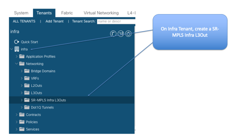
When you click create, it will take you the the screen where you put in the name of the Infra SR-MPLS (base) L3 Out, the L3 Out Domain, eVPN BFD policy QOS Policy, eVPN peer IP and AS Number

The Next Screen will take you to the page where you put in additional information like RID, vlan information, Interface, BGP-LU local IP (connected interface IP on ACI leaf) and Remote Peer BGP LU (connected first hop interface or SR domain). Also the BGP AS. Note as mentioned before, if you have a up and running fabric, do not put in a RID. Leave it blank. A Router ID was associated to overlay-1 VRF for every leaf and spine during intiial ACI day 0 Setup. This was done automatically by ACI and the IP was assigned from the TEP Pool. If you change this, it will cause disruption. Please read the warning and don’t do this !!!

The next figure shows the completed values for my lab setup for BGP-LU and for BGP-EVPN Loopback and Transport Loopback.

The Infra Tenant (base Tenant) SR-MPLS L3Out configuration is all complete. That was a one time configuration only. From now, for Tenants you can just associate the Tenant SR-MPLS L3Out to the Infra Tenant and that’s all it will take to bring up a L3 Out.
Let’s look at the Tenant SR-MPLS L3 Out configuration.
First go to the Tenant VRF and create a Route Target as shown below. I am using route Target import and route target export value of “route-target:as4-nn2:7:7”

Let’s go to the Tenant space and create a Route Map. We will associate this route map to advertise the BD IP out. This is the preferred way to associate L3 Out to BD even for normal L3 Outs.

Now, let’s go to the step of creating a SR-MPLS L3 Out object and associating that with the Infra SR-MPLS L3 Out as shown in figure below.

The diagram below shows how to associate the Tenant SR-MPLS out to the Infra SR-MPLS Out

Configuration is all done. Don’t forget to attach necessary contract between the user EPG and the L3Out EPG, just like you would do for a normal L3 Out. In the lab case, I just added the common-default contract as both provider and consumer between the user EPG and L3Out EPG.
Of course in our case, we just created a loopback in the PE router in a VRF to do ping test. In real life you would bring up a PE-CE connection, or you could even connect another SR-MPLS ACI L3 Out from the same Fabric or different Fabric there.
Let’s do a quick ping test to verify that things are working. Let’s ping from the PE VRF to the VM sitting on Tenant space.

Now that the configuration is all done and tested, you can easily see that adding new Tenant L3 Outs ( the SR kind) is a breeze !
In the next Section, I will show you some quick common sense troubleshooting commands in case things are not working.
Troubleshooting:
In case the ping is not working, first common sense thing to do will be to do a tcpdump on the VM sitting on the Tenant Space while pinging it from some source (generally a CE VM) in the SR-MPLS domain. If you see packets coming in, it means the return packets are not making it. If you don’t see packets coming in, you will know that the forward packets are not making it. In this case I will do a “sudo tcpdump -i ens160 -n -s150 -vv src host 188.188.188.188” on the VM in tenant space. Note in the below figure the capture was taken when I had some configuration errors. I had neglected to put the bgp next-hop-unchanged for the eVPN peer in the DC-PE and had not redistributed OSPF into BGP for ipv4 address family. Please see Figure 7 where I show how to use those knobs in BGP.

Packet Trace is also a very good way of checking on CSRs for details of packets. Basically I turn on packet trace with the following command. Then I ping and look at the packets.
The commands on the CSRs to be used are as follows:
- debug platform condition ipv4 188.188.188.188/32 both
- debug platform condition start
- debug platform packet-trace packet 128
To View:
- show platform packet-trace statistics
- show platform packet-trace summary
- show platform packet-trace packet 0 decode
To Stop:
- debug platform condition stop

Below I’m checking from DC-PE to see details of prefixes. Note how 100.64.7.0/24 (the BD IP subnet) is showing as next hop of 77.77.77.78 which is my transport loopback configured on ACI. “show bgp l2vpn evpn”

To look at connected-prefix-sid map, you can use the command “show segment-routing mpls connected-prefix-sid-map ipv4”. Please ignore the 10.60.60.0/24 as that is something I inserted manually while testing.

You can also look at a label for a prefix from bgp entry. “show ip bgp 3.3.3.3”

To look at forwarding table, you can do “show mpls forwarding-table” as shown below

You can see details of a prefix from CEF “show ip cef 3.3.3.3/32 detail”

Sometimes for troubleshooting, it is good to look at “show bgp l2vpn evpn” and confirming the evpn type 5 prefixes/next hops

You can look at forwarding table inside a VPNV4 VRF on CSR to confirm label stack. “show mpls forwarding-table vrf SM-T8 100.64.7.0 detail”

On ACI Border Leaf you can confirm correct next hop “show bgp l2vpn evpn vrf overlay-1”

You can check for labels of a prefix on ACI Border Leaf. “show ip route 3.3.3.3 detail vrf overlay-1”

Finally the normal commands that you use on ACI Border Leaf are still useful.
show bgp ipv4 labelled-unicast
show bgp l2vpn evpn
show bgp ipv4 unicast
show bgp process

📙 For your reference, I am including IOS-XR (ASR) based SR configuration snippet here.
Version Related Information:
RP/0/RSP0/CPU0:ifav-mpls-19-pe6#show ver
Thu Apr 20 16:44:28.944 UTC

Cisco IOS XR Software, Version 6.7.3[Default]
Copyright (c) 2020 by Cisco Systems, Inc.

ROM: System Bootstrap, Version 2.04(20140424:063844) [ASR9K ROMMON],

ifav-mpls-19-pe6 uptime is 1 year, 34 weeks, 2 days, 2 hours, 1 minute
System image file is "bootflash:disk0/asr9k-os-mbi-6.7.3/0x100000/mbiasr9k-rp.vm"

cisco ASR9K Series (P4040) processor with 8388608K bytes of memory.
P4040 processor at 1500MHz, Revision 3.0
ASR-9001 Chassis

2 Management Ethernet
20 GigabitEthernet
6 TenGigE
6 DWDM controller(s)
6 WANPHY controller(s)
219k bytes of non-volatile configuration memory.
2868M bytes of hard disk.
3915760k bytes of disk0: (Sector size 512 bytes).

Configuration register on node 0/RSP0/CPU0 is 0x102
Boot device on node 0/RSP0/CPU0 is disk0:
Package active on node 0/RSP0/CPU0:
iosxr-infra, V 6.7.3[Default], Cisco Systems, at disk0:iosxr-infra-6.7.3
    Built on Thu Nov 26 18:54:39 UTC 2020
    By iox-ucs-031 in /auto/srcarchive17/prod/6.7.3/asr9k-px/ws for pie

iosxr-fwding, V 6.7.3[Default], Cisco Systems, at disk0:iosxr-fwding-6.7.3
    Built on Thu Nov 26 18:54:39 UTC 2020
    By iox-ucs-031 in /auto/srcarchive17/prod/6.7.3/asr9k-px/ws for pie

iosxr-routing, V 6.7.3[Default], Cisco Systems, at disk0:iosxr-routing-6.7.3
    Built on Thu Nov 26 18:54:39 UTC 2020
    By iox-ucs-031 in /auto/srcarchive17/prod/6.7.3/asr9k-px/ws for pie

iosxr-diags, V 6.7.3[Default], Cisco Systems, at disk0:iosxr-diags-6.7.3
    Built on Thu Nov 26 18:54:39 UTC 2020
    By iox-ucs-031 in /auto/srcarchive17/prod/6.7.3/asr9k-px/ws for pie

iosxr-ce, V 6.7.3[Default], Cisco Systems, at disk0:iosxr-ce-6.7.3
    Built on Thu Nov 26 18:54:39 UTC 2020
    By iox-ucs-031 in /auto/srcarchive17/prod/6.7.3/asr9k-px/ws for pie

iosxr-common-pd-fib, V 6.7.3[Default], Cisco Systems, at disk0:iosxr-common-pd-fib-6.7.3
    Built on Thu Nov 26 18:54:39 UTC 2020
    By iox-ucs-031 in /auto/srcarchive17/prod/6.7.3/asr9k-px/ws for pie

asr9k-cpp, V 6.7.3[Default], Cisco Systems, at disk0:asr9k-cpp-6.7.3
    Built on Thu Nov 26 18:54:39 UTC 2020
    By iox-ucs-031 in /auto/srcarchive17/prod/6.7.3/asr9k-px/ws for pie

iosxr-gcp-fwding, V 6.7.3[Default], Cisco Systems, at disk0:iosxr-gcp-fwding-6.7.3
    Built on Thu Nov 26 18:54:39 UTC 2020
    By iox-ucs-031 in /auto/srcarchive17/prod/6.7.3/asr9k-px/ws for pie

asr9k-os-mbi, V 6.7.3[Default], Cisco Systems, at disk0:asr9k-os-mbi-6.7.3
    Built on Thu Nov 26 18:55:41 UTC 2020
    By iox-ucs-031 in /auto/srcarchive17/prod/6.7.3/asr9k-px/ws for pie

asr9k-base, V 6.7.3[Default], Cisco Systems, at disk0:asr9k-base-6.7.3
    Built on Thu Nov 26 18:54:39 UTC 2020
    By iox-ucs-031 in /auto/srcarchive17/prod/6.7.3/asr9k-px/ws for pie

asr9k-fwding, V 6.7.3[Default], Cisco Systems, at disk0:asr9k-fwding-6.7.3
    Built on Thu Nov 26 18:54:39 UTC 2020
    By iox-ucs-031 in /auto/srcarchive17/prod/6.7.3/asr9k-px/ws for pie

asr9k-ce, V 6.7.3[Default], Cisco Systems, at disk0:asr9k-ce-6.7.3
    Built on Thu Nov 26 18:54:39 UTC 2020
    By iox-ucs-031 in /auto/srcarchive17/prod/6.7.3/asr9k-px/ws for pie

asr9k-diags-supp, V 6.7.3[Default], Cisco Systems, at disk0:asr9k-diags-supp-6.7.3
    Built on Thu Nov 26 18:54:39 UTC 2020
    By iox-ucs-031 in /auto/srcarchive17/prod/6.7.3/asr9k-px/ws for pie

asr9k-scfclient, V 6.7.3[Default], Cisco Systems, at disk0:asr9k-scfclient-6.7.3
    Built on Thu Nov 26 18:54:39 UTC 2020
    By iox-ucs-031 in /auto/srcarchive17/prod/6.7.3/asr9k-px/ws for pie

asr9k-mini-px, V 6.7.3[Default], Cisco Systems, at disk0:asr9k-mini-px-6.7.3
    Built on Thu Nov 26 18:57:58 UTC 2020
    By iox-ucs-031 in /auto/srcarchive17/prod/6.7.3/asr9k-px/ws for pie

Boot device on node 0/0/CPU0 is mem:
Package active on node 0/0/CPU0:
iosxr-infra, V 6.7.3[Default], Cisco Systems, at disk0:iosxr-infra-6.7.3
    Built on Thu Nov 26 18:54:39 UTC 2020
    By iox-ucs-031 in /auto/srcarchive17/prod/6.7.3/asr9k-px/ws for pie

iosxr-fwding, V 6.7.3[Default], Cisco Systems, at disk0:iosxr-fwding-6.7.3
    Built on Thu Nov 26 18:54:39 UTC 2020
    By iox-ucs-031 in /auto/srcarchive17/prod/6.7.3/asr9k-px/ws for pie

iosxr-routing, V 6.7.3[Default], Cisco Systems, at disk0:iosxr-routing-6.7.3
    Built on Thu Nov 26 18:54:39 UTC 2020
    By iox-ucs-031 in /auto/srcarchive17/prod/6.7.3/asr9k-px/ws for pie

iosxr-diags, V 6.7.3[Default], Cisco Systems, at disk0:iosxr-diags-6.7.3
    Built on Thu Nov 26 18:54:39 UTC 2020
    By iox-ucs-031 in /auto/srcarchive17/prod/6.7.3/asr9k-px/ws for pie

iosxr-ce, V 6.7.3[Default], Cisco Systems, at disk0:iosxr-ce-6.7.3
    Built on Thu Nov 26 18:54:39 UTC 2020
    By iox-ucs-031 in /auto/srcarchive17/prod/6.7.3/asr9k-px/ws for pie

iosxr-common-pd-fib, V 6.7.3[Default], Cisco Systems, at disk0:iosxr-common-pd-fib-6.7.3
    Built on Thu Nov 26 18:54:39 UTC 2020
    By iox-ucs-031 in /auto/srcarchive17/prod/6.7.3/asr9k-px/ws for pie

asr9k-cpp, V 6.7.3[Default], Cisco Systems, at disk0:asr9k-cpp-6.7.3
    Built on Thu Nov 26 18:54:39 UTC 2020
    By iox-ucs-031 in /auto/srcarchive17/prod/6.7.3/asr9k-px/ws for pie

iosxr-gcp-fwding, V 6.7.3[Default], Cisco Systems, at disk0:iosxr-gcp-fwding-6.7.3
    Built on Thu Nov 26 18:54:39 UTC 2020
    By iox-ucs-031 in /auto/srcarchive17/prod/6.7.3/asr9k-px/ws for pie

asr9k-os-mbi, V 6.7.3[Default], Cisco Systems, at disk0:asr9k-os-mbi-6.7.3
    Built on Thu Nov 26 18:55:41 UTC 2020
    By iox-ucs-031 in /auto/srcarchive17/prod/6.7.3/asr9k-px/ws for pie

asr9k-base, V 6.7.3[Default], Cisco Systems, at disk0:asr9k-base-6.7.3
    Built on Thu Nov 26 18:54:39 UTC 2020
    By iox-ucs-031 in /auto/srcarchive17/prod/6.7.3/asr9k-px/ws for pie

asr9k-fwding, V 6.7.3[Default], Cisco Systems, at disk0:asr9k-fwding-6.7.3
    Built on Thu Nov 26 18:54:39 UTC 2020
    By iox-ucs-031 in /auto/srcarchive17/prod/6.7.3/asr9k-px/ws for pie

asr9k-ce, V 6.7.3[Default], Cisco Systems, at disk0:asr9k-ce-6.7.3
    Built on Thu Nov 26 18:54:39 UTC 2020
    By iox-ucs-031 in /auto/srcarchive17/prod/6.7.3/asr9k-px/ws for pie

asr9k-diags-supp, V 6.7.3[Default], Cisco Systems, at disk0:asr9k-diags-supp-6.7.3
    Built on Thu Nov 26 18:54:39 UTC 2020
    By iox-ucs-031 in /auto/srcarchive17/prod/6.7.3/asr9k-px/ws for pie

asr9k-scfclient, V 6.7.3[Default], Cisco Systems, at disk0:asr9k-scfclient-6.7.3
    Built on Thu Nov 26 18:54:39 UTC 2020
    By iox-ucs-031 in /auto/srcarchive17/prod/6.7.3/asr9k-px/ws for pie

asr9k-mini-px, V 6.7.3[Default], Cisco Systems, at disk0:asr9k-mini-px-6.7.3
    Built on Thu Nov 26 18:57:58 UTC 2020
    By iox-ucs-031 in /auto/srcarchive17/prod/6.7.3/asr9k-px/ws for pie

RP/0/RSP0/CPU0:ifav-mpls-19-pe6#
Configuration Snippets:
RP/0/RSP0/CPU0:ifav-mpls-19-pe6#show bgp ipv4 labeled-unicast summary
Thu Apr 20 16:20:06.471 UTC
BGP router identifier 119.119.119.106, local AS number 19
BGP generic scan interval 60 secs
Non-stop routing is enabled
BGP table state: Active
Table ID: 0xe0000000   RD version: 374
BGP main routing table version 374
BGP NSR Initial initsync version 2 (Reached)
BGP NSR/ISSU Sync-Group versions 0/0
BGP scan interval 60 secs

BGP is operating in STANDALONE mode.

Process       RcvTblVer   bRIB/RIB   LabelVer  ImportVer  SendTblVer  StandbyVer
Speaker             374        374        374        374         374           0

Neighbor        Spk    AS MsgRcvd MsgSent   TblVer  InQ OutQ  Up/Down  St/PfxRcd
50.50.50.37       0   100   75848 1162838      374    0    0 00:14:14          1 <<<<<<<<<< This session is with ACI BL
50.50.50.45       0   100   83089 1170908      374    0    0 00:11:35          1
50.50.50.49       0   100   75782  641464        0    0    0    49w1d Idle
110.110.110.33    0    19  849806  849676      374    0    0    1y10w         10 <<<<<<<<<<<<<<<, This session is with MPLS core router

RP/0/RSP0/CPU0:ifav-mpls-19-pe6#

RP/0/RSP0/CPU0:ifav-mpls-19-pe6#show running-config router bgp
Thu Apr 20 16:11:37.241 UTC
router bgp 19
bgp router-id 119.119.119.106
bgp cluster-id 19.19.1.6
mpls activate
  interface TenGigE0/0/2/0
  interface Bundle-Ether100
  interface TenGigE0/0/2/1.101
  interface GigabitEthernet0/0/0/0
!
address-family ipv4 unicast
  network 118.118.118.106/32
  network 119.119.19.106/32
  allocate-label all
!
address-family vpnv4 unicast
!
address-family ipv6 unicast
!
address-family vpnv6 unicast
!
address-family l2vpn evpn
!
neighbor-group L3VPN
  remote-as 19
  description +++L3 VPN with CORE-P +++
 update-source Loopback1
  address-family vpnv4 unicast
   import re-originate stitching-rt
   route-policy Allow_All in
   route-policy SET_L3VPN_NH out
   advertise vpnv4 unicast re-originated
   next-hop-self
  !
  address-family vpnv6 unicast
   import re-originate stitching-rt
   route-policy Allow_All in
   route-policy SET_L3VPN_NH out
   advertise vpnv6 unicast re-originated
   next-hop-self
  !
 !
 neighbor-group BGP-LU-DUAL-TEP
  description +++BGP-LU with Diff CP/DP-TEP- +++
  address-family ipv4 unicast
   route-policy Allow_All in
   route-policy BGP_Unicast_Prefix out
  !
  address-family ipv4 labeled-unicast
   route-policy Allow_All in
   route-policy BGP_LU_Prefix out
  !
 !
 neighbor-group BGP-LU-Single-TEP
  description +++BGP-LU with Same CP/DP-TEP- +++
  address-family ipv4 labeled-unicast
   route-policy Allow_All in
   route-policy BGP_LU_Prefix out
  !
 !
 neighbor-group EVPN_eBGP_DUAL_TEP
  ebgp-multihop 10
  description +++EBGP-EVPN with Diff CP/DP-TEP +++
  update-source Loopback1
  address-family l2vpn evpn
   import stitching-rt re-originate
   multipath
   route-policy Allow_All in
   allowas-in 5
   route-policy EVPN_NH_MOD out
   as-override
   advertise vpnv4 unicast re-originated stitching-rt
   advertise vpnv6 unicast re-originated stitching-rt
  !
!
neighbor-group EVPN_eBGP_Single_TEP
  ebgp-multihop 10
  description +++EBGP-EVPN with same CP/DP-TEP +++
  update-source Loopback2
  address-family l2vpn evpn
   import stitching-rt re-originate
   multipath
   route-policy Allow_All in
   allowas-in 5
   route-policy Allow_All out
   as-override
   advertise vpnv4 unicast re-originated stitching-rt
   advertise vpnv6 unicast re-originated stitching-rt
   next-hop-unchanged
  !
!
neighbor-group EVPN_eBGP_DUAL_TEP_Reflection
  ebgp-multihop 10
  update-source Loopback1
  address-family l2vpn evpn
   import stitching-rt re-originate
   multipath
   route-policy Allow_All in
   allowas-in 5
   route-policy EVPN_NH_MOD out
   as-override
   advertise vpnv4 unicast re-originated stitching-rt
   advertise vpnv6 unicast re-originated stitching-rt
   next-hop-unchanged
  !
!
neighbor-group BGP-LU-DUAL-TEP_EVPN_Reflection
  description +++EBGP-EVPN with Diff CP/DP-TEP-USED FOR BL-2-BL-REFLECTION +++
  address-family ipv4 unicast
   route-policy Allow_All in
   route-policy Allow_All out
  !
  address-family ipv4 labeled-unicast
   route-policy Allow_All in
   route-policy Allow_All out
  !
!
neighbor-group EVPN_eBGP_Single_TEP_Reflection
  ebgp-multihop 10
  description +++EBGP-EVPN with same CP/DP-TEP-USED FOR BL-2-BL-REFLECTION +++
  update-source Loopback2
  address-family l2vpn evpn
   import stitching-rt re-originate
   multipath
   route-policy Allow_All in
   allowas-in 5
   route-policy Allow_All out
   as-override
   advertise vpnv4 unicast re-originated stitching-rt
   advertise vpnv6 unicast re-originated stitching-rt
   next-hop-unchanged
  !
!
 neighbor-group BGP-LU-Single-TEP_EVPN_Reflection
  address-family ipv4 labeled-unicast
   route-policy Allow_All in
   route-policy Allow_All out
  !
!
neighbor 50.50.50.37
  remote-as 100
  use neighbor-group BGP-LU-Single-TEP_EVPN_Reflection
  description +++BGP_LU-Ifav42-leaf1+++
!
neighbor 50.50.50.45
  remote-as 100
  use neighbor-group BGP-LU-Single-TEP_EVPN_Reflection
  description +++BGP_LU-Ifav42-leaf1+++
!
neighbor 50.50.50.49
  remote-as 100
  use neighbor-group BGP-LU-Single-TEP_EVPN_Reflection
  description +++BGP_LU-Ifav42-leaf1+++
!
neighbor 118.118.118.1
  remote-as 19
  use neighbor-group L3VPN
  description +++BGP_VPNv4/v6-MPLS-PE_CORE+++
!
neighbor 151.151.151.1
  remote-as 100
  use neighbor-group EVPN_eBGP_Single_TEP_Reflection
  description +++BGP_EVPN-Ifav42-leaf1+++
!
neighbor 110.110.110.33
  remote-as 19
  use neighbor-group BGP-LU-DUAL-TEP
  description +++BGP_LU-MPLS-PE_CORE+++
!
vrf site3_emc0_ubfd
  rd auto
  address-family ipv6 unicast
   network 2001:100:100:1::/64
  !
  neighbor 2003:200:10:10::11
   remote-as 1900
   ebgp-multihop 10
   update-source Loopback100
   address-family ipv6 unicast
    route-policy pass-all in
    route-policy pass-all out
   !
  !
!
References:
Validated Design for Cisco ACI to SR-MPLS Handoff
Hardware and software support
Packet Walk SR-MPLS Handoff Architecture
ACI SR-MPLS Handoff Configuration Guide
Multi-Site Configuration Guide for ACI Fabrics
Segment Routing: Cutting Through the Hype and Finding the IETF’s Innovative Nugget of Gold
Segment Routing Configuration Guide, Cisco IOS XE Release 3S
Segment Routing Configuration Guide for Cisco CRS Routers, IOS XR Release 6.2.x
SegmentRoutingConfigurationGuide,CiscoIOS XE Gibraltar16.11.x
Segment Routing 101 and the Future of MPLS by Aviat Networks
Understanding EVPN Pure Type-5 Routes – Juniper
A Series of really good youtube Videos on Segment Routing from Juniper Distinguished Engineer
Very nice short hands on Demo on Segment Routing by Juniper
NANOG Recorded Presentation on Segment Routing (youtube)
Excellent Cisco Deck on SR Traffic Engineering
Deploy Layer3 EVPN over Segment RoutingMPLS [Ospf / iBGP] in Nexus 3000
Really Good Cisco Live: Introduction to Segment Routing – DGTL-BRKRST-2124
BGP Unlabeled and Labeled Unicast in the Same Session Configuration: Cisco XE 17
BGP Quick Reference
4 Byte AS Numbers Explanation
netmindblog: OSPF Segment Routing L3VPN and TE