Previously I had written an article on Deploying MSO on Cisco Application Service Engine (OVA Based SE). That article was updated on 7/6/2020 to include the connectivity discussions and install instructions for release 3.0.2d MSO running on SE 1.1.3d.
Added on 4/26/2021
Current Release you should use on AWS is as below (until such time as ND on cloud comes out):
SE: 1.1.3e
MSO: 3.1.1i
I have recently got a few requests to also do a writeup / install guide on MSO 3.0.2d with SE 1.1.3d running on AWS (using AWS AMI image).
The Connectivity of SE 1.1.3d on AWS is very similar to the OVA version. Each SE has 2 interfaces:
SE 1.1.3d AWS AMI has 2 interfaces:
- Data Interface — The purpose for this interface is:
- Cisco Application Services Engine Clustering.
- App to app communication.
- Access the management network of the Cisco ACI fabric.
- All app to ACI fabric comunications.
- Management Interface – The purpose for this interface is:
- Accessing the Cisco Application Services Engine GUI.
- Accessing the CLI over SSH.
- DNS and NTP.
- Firmware uploads.
- Intersight device connector.
- If you need your MSO to manage ACI Fabrics that are in different locations, you will need that interface to have a Static Public IP (Elastic IP)
- The management interface would also require a Static Public IP (Elastic IP), so you can browse to the SE/MSO.
SE Cluster consist of 3 SE nodes. So, a typical SE cluster install on AWS will require 6 AWS Elastic IPs as shown in the diagram below.

Below I will show step by step on how to Installing SE 1.1.3d on AWS and then install MSO App 3.0.2d on that installed SE.
The first item to make sure is that you have enough AWS Elastic IPs free in the region that you intend to install SE/MSO.
To do this, log into the AWS Console and go to EC2. You need to have admin or equivalent privileges on your AWS account, so you can create VPCs, Spin up appropriate EC2 instances, etc, etc.

On the EC2 menu, click on Elastic IPs and make a note of how many elastic IPs you are already using. In my example below, I am already using 3 elastic IPs

Next, click on Limits, to see what your current Elastic IP Limit is for your AWS account

As you can see below my limit is 5. This is the default limit that AWS has on new accounts.. Out of my 5 elastic IPs, I am already using 3. I need 6 Elastic IPs altogether for the SE cluster, so obviously this will not work. To increase the limit of Elastic IPs, click on “Request limit increase” as shown in the figure below.

Next, Choose Service Limit increase and fill up the ticket form per your needs. I show you my example below.


After you hit Submit, you will get an automated Case ID from AWS. Generally the case will be resolved very quickly. From my experience the case gets resolved in 5 minutes and I have my extra elastic IPs in 20 minutes available in the account.

Next, you need to create the SSH key pair that you will use for ssh to the SE nodes. If you already have a key pair created in the region that you want to reuse, you can skip this section.
To create a ssh key pair, first select the region where you intend to deploy the SE cluster. In my example below I choose the N. Virginia Region., go to EC2.

Next click on Network & Security / Key Pairs

Click on Create Key Pair

Fill in the rest of the information as shown in the figure below and click create key pair

Make sure to download the private key and store it in a safe place on your local machine

The Next step will be to create a VPC in that region, to host your SE Cluster
To do so, first Navigate to VPC section in AWS Console. Please make sure that the correct region is selected where you want to host the SE Cluster (step 1 in figure below). In my case I’ve chosen N. Virginia region.

Next Create your new VPC for hosting the SE cluster

Finish creating your VPC as shown in the diagram below. For the CIDR block, you can choose between /16 and /24. I have chosen 10.176.176.0/24 in my example. I named my VPC MSO-VPC

The screen will now confirm that your VPC was created.

Next, you need to create an IGW (Internet Gateway) for the VPC. To do this, go to VPC / Internet Gateway and click Create Inteernet Gateway.

Tag the IGW with an appropriate name. In the example below, I call mine Cisco-MSO-IGW. Click Create Internet Gateway

Now, you need to attach that IGW you created to the VPC you created. Click Actions and Attach to VPC

Now Choose the VPC that you created for MSO as shown below.

Next you need to edit the route table for the VPC and add the IGW as the next hop for your intended reachability. To do this go to VPC/Route Tables, Select you MSO VPC and click edit routes

next, Click Add Route, Put in from where you want to access (I put 0.0.0.0/0) in my case, Select IGW and select the IGW you built

You will now get confirmation that your routes was successfully added to VPC.

You can also confirm that your Route to your destinations using IGW as next hop was added to your VPC

Now, we need to get the SE AMI image and start installing. Click on Services and type in market and choose AWS Marketplace Subscriptions

Click on Manage Subscriptions

Next Click on Discover products

In the search bar, type in “cisco services engine” and then choose Cisco Application Services Engine Version 1.1.3d

Next Select “Continue to Subscribe”

Accept Terms

Click on Continue to Configuration

Next, Choose your SE image Version, your region and click on Continue

Next, choose “Launch CloudFormation” and click Launch

On Create Stack, click Next

Now Specify the Stack Details. Please see figure notes below to help populate the fields and modify based on your requirments.


Go to the very bottom of the screen and click Next again.

At this time, you can review the Configuration Details. If all looks good, click on Create Stack. If not, click on Previous and fix it.

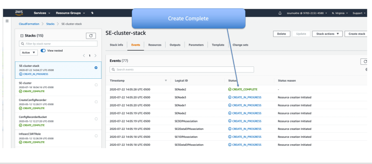
The Cloud Formation Template was finished and submitted. It will now run and spin up your SE Nodes. Click on the refresh button once in a while to see progress.

After a while you will see that the message will say “Create Complete”
If you go to EC2/Network Interfaces you can verify that each SE has 2 interfaces a Data Interface and a management Interface

Now, go to EC2/Instances and you will see the instances running. Initially the Status Checks will say initializing. Refresh the screen till it shows the status Checks are “2/2 checks passed”

Get the Public IP of one of the SE Nodes. I prefer to work on the 1st node, “SE-node1” in my case (based on my naming convention).

Now, on your local machine, go to the directory where you stored your private key that you made earlier. do a chmod 400 for that key

Now ssh to the se-node1 using the key. Username must be “rescue-user”

Use “acidiag health” command periodically to check the health till the K8s Cluster is healthy. It will say “All Components are healthy”

You can also check the Cluster config with the command “acidiag cluster get config”

To see who the master nodes are you can use “acidiag cluster get masters”

Similarly to see which nodes are K8s workers you can use the “acidiag cluster get workers” command. You will notice that it does not give you any output. That is because in this setup there are no dedicated workers. The masters are also acting as workers

To show you this, I ssh’d in as root on se-node1 as you can see below. I see from kubectl commands that the master is not tainted. That is why they can also run K8s workloads. Dedicated masters generally have a taint such as master:NoSchedule

Your SE 1.1.3d install is now complete. You now need to install the MSO App on the SE. To do this you can use:
- SE UI
- ssh session to SE

First download the MSO code to your local machine or a web server. You can download from CCO or from APP Center.

Once Download is complete, you need to upload the code to SE. You can do this via SE UI or via scp.

For the SE UI Method, point your browser to one of the SE nodes. I prefer to use se-node1. Log in with username of admin and password of rescue-user that you had configured in the Cloud Formation Template.

Go to Apps and Click on Install Apps

From here you can upload the MSO App using either local or remote location

If you were going to use scp method to upload code, then you could do so also. Upload the code to /tmp directory using scp as shown below.

Now that the code is uploaded, you need to install using acidiag app commands. acidiag app –help lists you all the available commands.

to Install the MSO app, use the acidiag app install command as shown below

check with “acidiag app show” command. Make a note of the app ID. In this case it is cisco-mso:3.0.2d

At this time, if you looked from SE UI, on the APP menu you will see that the MSO APP is ready to be Enabled. You could click the Enable button to continue from the UI if you wished.

If you decided to keep using the ssh cli session, you can execute the acidiag app enable command using the app ID that you noted before

After executing acidiag app enable command, check once in a while with “acidiag app show” command. Make note of the operStage and the operState values. When the system is ready, the values will show as:
- ‘operStage’: ‘Enable’,
- ‘operState’: ‘Running’,

When the system is ready, you sill see on the SE UI that the button will say “Launch App” You could click that to launch the MSO. Alternatively you could point your browser directly to https://SE_IP/mso/login

Login to the MSO using the following credentials:
- username: admin
- Password: We1come2msc!

Once Logged in, you will be prompted to change your default admin password for the MSO. After that, you are ready to do the basic configs and add your ACI sites to MSO.

Your MSO is now ready to be used !
https://www.cisco.com/c/en/us/td/docs/data-center-analytics/service-engine/APIC/1-1-3/getting-started-guide/cisco-application-services-engine-user-guide-113.htmlReferences:
- Cisco ACI Multi-Site Orchestrator Installation and Upgrade Guide, Release 2.2(x)
- Cisco Application Services Engine Installation Guide, Release 1.1.2
- Cisco Application Services Engine Installation Guide, Release 1.1.3
- The SE OVA can be downloaded from CCO and the MSO code running on SE can be downloaded from Cisco App Store
Thanks a lot for writing this…
You are welcome Imran. Just f.y.i. The doc should be good, but it’s still getting reviewed by other folks. Also,MSO on AWS is not officially supported at the moment for physical fabric orchestration. This is purely because QA testing has not been done. I have worked with customers who actually did this for a POC ( in a previous release) and they had no complaints. So, my data point is that it works well. However for prod use to manage physical fabrics with AWS hosted MSO, I would wait till Cisco officially supports it.
Doc has been reviewed by engineering and I’ve made the necessary changes based on thier review., so I took the RED banner off that said Under Review. It’s good now.