Updated 7/06/2020 : Please skip to the SE install section: SE Release 1.1.3d (OVA) Install Instructions:
Update 1/21/2021: Current and recommended release of SE is 1.1.3e.
Starting with Release 2.2(3) of MSO, Cisco Application Service Engine (CASE) can be used to host the MSO. Previous to this release MSO could only be installed in a docker-swarm environment.
The older docker-swam based MSO is still a valid option, but the new version of MSO running on CASE has advantages and I highly recommend that folks migrate to that. Migration can be done very easily by pulling in a backup and restoring the backup to the CASE based MSO. If you are just starting off with MSO, I strongly suggest you start off with *test out MSO running on CASE. I suspect that in the future the CASE based MSO will become the defacto choice for the majority of customers.
* Added on 5/11/2020:
Caution: At the moment the SE OVA cluster recovery has not been sorted out yet. The SE cluster requires a minimum of 2 SE nodes up to be operable. If you have 2 SE nodes fail, then the SE cluster will be inoperable and cluster recovery process has not been defined at the moment. I will update this blog as soon as that feature is developed and I test it out.
* Added on 5/20/2020:
SE Release 1.1.3 has just been released. However MSO ( current release of 2.2.4e or 3.0.1i) is not qualified to work with that. The next release of MSO — 3.0.2 (which has supposedly much richer features) will work with SE 1.1.3.
MSO Version 2.2.4e or 3.0.1i work fine with SE1.1.2
* Added on 7/6/2020:
- SE release 1.1.3d has been released on 7/3/2020.
- MSO release 3.0.2d has been released on 7/3/2020
- MSO release of 3.0.2d works fine with SE releae 1.1.3d.
- for MSO release 3.0.3 you need to be on SE rlease 1.1.3d (added this note on 9/16/2020)
- I have included screenshots (with explanation) on installing SE release 1.1.3d below in this writeup
So What Exactly Is CASE ?
CASE stands for Cisco Application Service Engine. To make it easier for myself, I will just refer to it from here as Service Engine or SE.
SE is an appliance that serves as a common platform for deploying specialized Cisco Data Center applications. One of these applications is the newer MSO that we will talk about in this writeup.
SE runs Kubernetes (K8s) under the hood. Because of the K8s based architecture it inherently gives you built in resiliency for your apps, lets you upgrade apps easily (recall the rolling upgrade built into K8s). If you have worked with the docker-swarm based MSO, and have had to upgrade your MSO at any time, you probably (like me) have struggled with upgrading MSO, trying to get the right version of python and associated modules to make it work (and probably opened a TAC case or two ultimately to get it going). The MSO that runs on SE can be upgraded with just a few clicks in the GUI making it very convenient and easy for operations. Also, I have found the SE based MSO to be much more snappy/responsive.
Cisco Application Services Engine is deployed as a cluster of three service nodes. This clustering provides reliability and high-availability software framework.
7/13/2020: With the release of SE 1.1.3d, the architecture has changed. If you are looking at 1.1.3d onwards, please directly go to the section:
SE Release 1.1.3d (OVA) Install Instructions:
and follow from there
Cisco Application Service Engine can be deployed in two modes :
Fabric Internal Mode:
As of this writing (April 30th, 2020), this mode is only available in the hardware base Service Engines (UCS-C series server appliances). In this mode the hardware based Service Engine Cluster is directly connected to ACI leaves (much like APICs). Then you have to install the ISO SE image on them and do the basic configuration on those SEs. You finish off the install by installing the SE APP on the APIC and discovering the Service Engines. Once this Hardware Based SE has been installed/discovered from the ACI App, you can start deploying approved Cisco Data Center management applications on that, like Network Insights Advisor and Network Insights Resources.
In this mode, inband management configuration has to be done for the ACI fabric to talk to the SE. Keep in mind that you can still keep using Out Of Band Management for all your other stuff if you were doing that before. Even the SE mgmt interface will be on a OOB network. The Inband management interfaces of these SEs are just for SEs to gather information from the ACI Fabric.

Fabric External Mode:
In this mode, you don’t need to have the Hardware SE appliance from Cisco (though you can). In this mode, you can’t (as of yet, it may be coming later, but I really don’t know for sure), use Inband Fabric Configuration for the SE to talk to the Fabric. This also means that NIA and NIR app in this mode will give you limited functionality. However there are other applications that will work just wonderfully in this mode, like the MSO to start off with.
In Summary, Fabric External Mode can be configured on:
- Hardware Based SE using the ISO image
- AWS – AMI (Amazon Machine Image) form factor
- OVA – VMware form factor
- KVM form factor
In this write up, my intention is to take you step by step on how to install the OVA based SE on VMware and then install the appropriate MSO image on the SE.
I also added a section to this document that shows in detail (with screnshots) on how to upgrade/downgrade the SE based MSO Code using GUI or CLI.
Remember that at the end of the day, the SE is an appliance. All the complexities of Kubernetes is hidden under the hood and as a user you cannot execute the standard K8s commands unless you go in as root. You will not be able to go in as root unless you work for Cisco TAC / Professional Services or equivalent.
For the curious, I will go in as root and show you some screen captures of what happens under the hood in SE cluster in the K8S level.
Let's Get Going:

(you might want to skip this and go to the section"SE Release 1.1.3d (OVA) Install Instructions" for SE 1.1.3d install and then come back to the "Installing MSO on SE" section)
Before we start let’s talk about the pre-requisites. In a production environment, you will need the following.
- 3 esxi hypervisors with version 5.5 or higher of esxi (in my lab I also tested with version 7.0). Also recommend that the esxi’s are managed by vCenter, but not totally necessary
- each esxi needs 16 vCPUs
- each esxi needs 48GB of RAM
- each esxi needs 600 GB Hard Disk Space
- The SE OVA can be downloaded from CCO and the MSO code running on SE can be downloaded from Cisco App Store
In a lab environment you can get away with only 1 esxi and you can install 1 SE Node instead of 3.
Assuming you already have your esxi infrastructure installed and ready to go, let’s proceed from there. In this example, I will assume you are using vCenter to manage your esxi hosts.
Before you start, please make sure to go to vCenter and make sure that you enable NTP and sync up correct time on all your ESXi’s. This is always good practice.

Download the SE image from CCO. For this particular scenario, you need to download the OVA image.
In vCenter right click on host and then “Deploy OVF Template”. ( You could also download the OVF file in your vCenter Content Library and install from there if you wanted to)

Next just follow through and go like any OVA/OVF install. In my case I name my First SE VM, “se01”

I put it on the first host

On the next screen just keep going by hitting the “NEXT” button

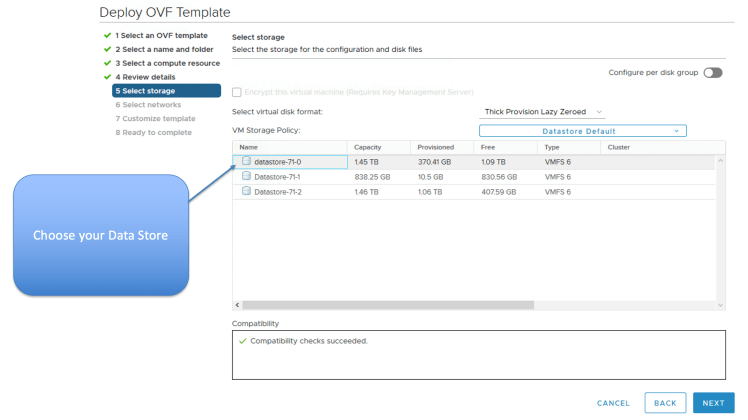
Choose your Storage for the SE VM

Choose your vswitch or dvs port group, such that you can can access the SE VMs from your local machine. In my case, I just chose the vSwitch VM Network port group.

Everything above is pretty standard stuff. Now you have to fill in the OVF template, so please go a bit slow here so you don’t make mistakes.
For the first node”
- put in Node ID: 1,
- make up some serial number in my case, I put “serial1”
- put in hostname “se01” in my case
- put in the rescue-user password and confirm
- for Domain name, please don’t append se01. This is not the FQDN. This is just the domain name for the node. If you don’t match this up on all 3 nodes, your SE nodes will not be able to join the cluster and you will have to start over. In my case I just put in “cisco.com”
- put in the ip / mask of this SE
- put in the gateway IP
- put in the Application Overlay Network IP subnet (this is the internal K8S network that has the K8S pods (apps) attached to). Please make sure that this is unique and not being used in your network. In my case, I just choose the default of 1.1.0.0/16. Please match this for the others SE’s also to make it easier on yourself.
- put in the Service Network IP subnet. (This is where the internal K8s Services load balancer / Cluster IP is obtained from). Please make sure that this is unique and not being used in your network. In my case, I just choose the default of 2.2.0.0/16. Please match this for the others SE’s also to make it easier on yourself.
- Populate the NTP Server(s)
- Populate the DNS Server(s)
- Populate the Domain Search List
- In the Cluster Configuration Section Make sure to check the check button for first Node in the Cluster. Subsequently, for the other SE Nodes you will not check this option.
- In the List of IP,Serial Numbers for peer nodes, please be careful. This has to be done in a very specific format. Here you will put in the IP and Serial number of the other 2 peer nodes in a specific format. In my case, my nodes and serials (I gave ) are:
- 10.201.35.100 serial1
- 10.201.35.101 serial2
- 10.201.35.102 serial3
- So, when deploying the first node (se01), I will put in the field here as 10.201.35.101,serial2 10.201.35.102,serial3
- If you don’t do this just right your install will bomb on you and when you boot the SE after install, you will be taken to the initial CLI setup screen. You could continue and configure properly from the CLI screen, so you do get another chance, but it’s a pain to have to type in all that again. Besides you will be doing the initial CLI entry from the vmware console and you won’t be able to cut and paste, which makes it even a bigger pain when you have to enter the debug token value for the second and third nodes
- Note in the next release of SE (1.1.3) you will not have to put up with this problem. The SE Serial numbers will be auto-generated ! Meaning it will not ask you to put in the Serial Numbers any more, so, less chances to get the format wrong.
- dbgtoken value. For the first node just put in some string. In my case, I put in abcdefabcdef. on subsequent SE Nodes, you will put in the value of the “acidiag dbgtoken” value from the first node there (by ssh’ing to first node).


Once you are done with that, the OVF will install and when it’s done, it will be in shut down state. Boot up se01 VM now from vCenter and web console into it from vCenter.
Watch it boot. If the boot goes some way and then goes to the screen where it takes you to the CLI Initial Setup screen, then you have probably put in the peer IP, Serial number in the wrong format. You can try to put it in now from CLI Startup screen. as shown below. Hopefully you did it right the first time, so you don”t have to do it again. In case you needed to do it, from CLI Startup screen this is what it would look like for SE01.

Note: If you were installing in lab and wanted to get away with one SE Node only, then:
- make sure to choose 1 Master only.
- Don’t put anything in the peer node entry
Once you are done with SE Node one (se01) in my case, install SE node 2 (se02) in my case. Please install in the 2nd esxi. I will paste my entries below for se02 so you can follow through if you wanted to.
Please make sure that in the last entry for the dbgtoken, ssh to se01 and do a “acidiag dbgtoken” then enter that value for se02 as shown below. When SSH’ing in, please use username of rescue-user and the password that you configured earlier


Repeat similar steps for se03, put in third esxi.


Finally after about 20 minutes, the K8S Cluster will be up and ready. Check by doing “acidiag health” in any of the SEs. Wait till the output says “All components are healthy”

Note: In case clustering does not want to come up, chances are that some parameter in the setup was not entered correctly. TAC will have to go in as root and look at “/confg/run-ovf-prepare.log” to find out which parameter was incorrect.
You are all done installing the SE Cluster !!!
Next Step, let’s install the MSO Code.
Installing MSO on SE:
From from Cisco App Store or from CCO, download the MSO code. The extension of the file will be .aci

Once downloaded, scp the file to any one (and one only) of the SEs. In my case, i download to se01.
Note: Want to make a point here. Remember that the underlying architecture is K8S based. The MicroServices that make up the MSO app will automatically be spread out amongst all the nodes. This is a function of Kube-Schedular. Please see “Distribution of MSO Apps” in figure 27. You can also see the distribution directly from the MSO GUI, please see screenshot Figure 20.7.
The kube-api server of the master nodes will keep track of the services and initiate kube-schedular to bring them up on another node if there is a failure. This is an inbuilt function of K8s. For that reason, you don’t have to install the MSO app on different SEs. Just install on any one SE node and K8S will take care of the rest.
scp “Cisco-MSO-2.2.3 (1).aci” rescue-user@10.201.35.100:/tmp

Check to make sure that the code is there on that SE (se01 in my case)

In this particular case, the MSO code has spaces and brackets in the name. I don’t want to deal with that. So, I’m just renaming it to get rid of those special characters.

Next on the SE, do a “acidiag app -h” to see all the acidiag app commands available.

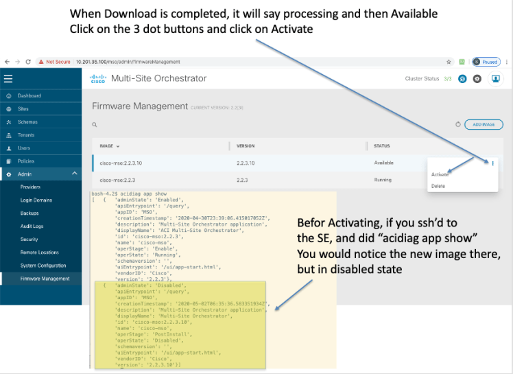
Install the MSO App with “acidiag app install image_name.aci”
Follow with “acidiag image show image_name” as suggested

Check the status with “acidiag app show”
Follow with “acidiag app enable $ID” where $ID is the id of the app as shown below

Repeat “acidiag app show” few times, till you see:
- ‘operStage’ : ‘Enable’
- ‘operState’:’Running’


All done ! You can now point your browser to any of the SE IP addresses and the MSO GUI will come up.
Please log in with the default credentials of:
- username: admin
- password: We1come2msc!

Now you could set up the MSO from scratch for a new install or you can backup your install from a previous MSO and restore it here. After that you are ready to go.
Some Items on MSO worth Mentioning:
- system Logs: this was available in the Docker Swarm version also
- System Status: This is only available on the SE version of MSO
- firmware management: for one click upgrade — Only avaialble on SE version of MSO


Upgrading/Downgrading SE based MSO Image
For the SE based MSO, upgrading / downgrading can be done:
- directly from GUI as shown below
- or can be done by scp’ing the image to any SE node and then use the following commands
- a) acidiag app install <new_image_name>,
- b) acidiag app show to find the imageID
- c) acidiag app enable <imageID> # to activate the new image
Direct GUI Method to Upgrade/Downgrade:


A Look At the Kubernetes infrastructure for SE, for the Curious
As mentioned before, you will not have access to the K8s infrastructure as this is an appliance and all the complexities of K8s is hidden from the user. If you could go in as root (being a Cisco employee/partner), you will be able to get access to the underlying K8s infrastructure and inspect it.
Before Installing MSO app:


After Installing MSO app:


SE Release 1.1.3d (OVA) Install Instructions:
added on 7/6/2020
Pre-requisites:
- esxi 5.0 or above
- CPU: 16
- Memory: 48GB
- Hard Disk 230 GB
SE Release 1.1.3d is now available as of 7/3/2020. You can install this release of SE and install MSO release 3.0.2d on there as a running K8s application. ( Note that MSO release 3.0.2d will not install on a previous version of SE)
Below, I show you instructions with screenshots on how to do this. Note, that in this case, I am installiing the SE in a lab and will only use a 1 Node Master (This is O.K. for me, since this is a lab and I don’t want to use up extra disk space. Also note that this release of SE uses less disk space compared to the previous release. The previous release used 600 GB where as this release only uses 230 GB)
Before Installing the SE Release 1.1.3d OVA, it is essential to understand the architecture of this version of SE.
SE 1.1.3d OVA has 2 interfaces:
- Fabric Interface (fabric0) — this is also known as the data interface and is meant to connect to L3Out connection from ACi Fabric Leaves. The purpose for this interface is:
- Cisco Application Services Engine Clustering.
- App to app communication.
- Access the management network of the Cisco ACI fabric.
- All app to ACI fabric comunications.
- Management Interface (mgmt0) – this is also known as management interface and needs to connect to OOB network. The purpose for this interface is:
- Accessing the Cisco Application Services Engine GUI.
- Accessing the CLI over SSH.
- DNS and NTP.
- Firmware uploads.
- Intersight device connector.
The Diagram below depicts the connectivity that’s required. Keep in mind that you cannot just use 1 interface, you have to have both interfaces connected to the proper port groups in the esxi dvs/vswitch.

In my setup, to make it easier, I have just connected the 2 interfaces to different sub-interfaces of an upstream router. This just happens to be the ISN router where ACI Spines connect to (through the vCSRs). That way both interfaces are functional and I have both Data and Management interfaces that can be used for their respective purpose. If I had just connected the mgmt interface to the mgmt port group, I would be able to ssh to SE and reach any destination, but from the app that runs on the SE ( in this case MSO), I would only have management access (ssh/web). However, the MSO app would not be able to reach the APICs, Radius Server, etc, etc as that would require the Data Interface (in essence I would have a non functional MSO).
The connectivity I am using is depicted below. Note that you generally would want to connect the fabric0 Interface to an L3Out on some ACI Leaf. (For NIA/NIR application running on SE that L3Out needs to have connectivity to the inband of the APIC, either through route leaking from mgmt tenant VRF or creating the L3Out for inband external on mgmt VRF. You could also connect that L3Out to an external router that is in the same routing domain that the SE data interface (fabric0) connects to.)
Note: You can also put both the data interface and fabric interface on the same subnet (i.e. connect it to the same dvs/vSwitch port group). That is sometimes an easier way to do it. Ofcourse each interface would have to have a different IP in the same subnet. Update: 11/3/2020: I’ve tested the same interface install in 1.1.3d and it has issues. The install is generally not successful, and if you do manage to get it up and running, you will notice from K8s level, that the pods continiously go to crash mode and then recovers. In other words it’s not stable. A bug has been raised for this (CSCvv82660), however I’m not sure when or if the bug will get fixed in a SE release, given that Nexus Datacenter (the next gen SE), is around the corner and this is where everything will be going. Incidentally, the first release of MSO that can run on ND is 3.2. The problem occurs in single node or clustered node install for SE 1.1.3d. Having the fabric and mgmt interfaces in different subnets works flawlessly.
Update 1/12/2021: SE 1.1.3e works fine with both data and fabric interfaces in same subnet.

Now that we understand the connectivity requirements, installing the OVA is like any other OVA
Name the SE VM and choose the vCenter DC

Note that this release of SE only uses 230 GB of disk space compared to 600 GB for the previous release

Choose your Data Store
On this SE VM there are 2 vNICs and both need to be connected.
- mgmt (management interface)
- fabric0 (data interface)

Configure the Host Name, rescue-user password and management IP/gateway

Enter the Cluster Name, the other SE (K8s) master IPs, and this masters dbgtoken value
- Note the following:
- In this case, since I will only install a 1 node cluster of SEs, I won’t put anything in the Peer masters IP address
- Since this is the 1st master, the dbgtoken value is some arbitary value, in my case I just put “abcdefabcdef”

Keep populating the rest of the fields as shown in the diagram below. Note, that since this is the 1st (and only) master in this deployment, Idid not check the “Download config from Peers…” option

Verify the summary config and hit “Finish” to compete the configuration

After install is done, go to vMware console for the SE VM, log in as “rescue-user” and your defined password.
Check the health of the SE (K8s) cluster by executing “acidiag health”. In my single node cluster it took less than 15 minutes for it to be in ready state

You are all done installing the SE release of 1.1.3d. Now follow from Figure 13 onwards for installing your version of MSO SE code.
Alternatively, you could also use the SE GUI for installing the MSO App as shown below. The UI username is: admin and password is the rescue-user password that you set during install.

Accessing the MSO UI directly
Once your MSO is up and running, if you wanted to access the MSO directly point your browser to https://<mgmtIPofSE>/mso/login (if you pointed your browser to https://<mgmtIPofSE>/, then you would land up on the SE device UI)
Additional SE Cluster Health view commands
- acidiag health :Checks the cluster health
- acidiag cluster get config : Shows the cluster config
- acidiag cluster get masters : Shows the K8s Master Nodes
- acidiag cluster get workers : Shows the K8s Worker Nodes
- acidiag app show : Shows installed apps
acidiag health

acidiag cluster get config

acidiag cluster get masters

acidiag cluster get workers

* Note: in the output of “acidiag cluster get workers” command, you will notice that the output of the command does not show any workers. The reason for that is because in this (lab environment), we have only 1 K8s (SE) Node and the Node is configured as a master.
Question: The next question you might ask is “if that node is a master then how are we running the MSO app on that master, would the app not need a K8s worker node to run the app ? “
Answer: The reason that you can run app on the 1 node master is that the taint has been removed from the master, so the master also acts as a worker. This is obvious when you look at it from root. You will notice that there are no taints configured for this 1 node K8s Master.
kubectl get nodes -o wide (after logging in as root — will need token to do that)

kubectl describe node dmz-se01 | grep -i taint
(notice there are no taints in the master

In a typical dedicated K8s Master Node configuration, the Master Node will be tainted with a “master:NoSchedule” taint, so that workloads will not be deployed on it. Below is an example from a typical K8s Master Only Node Taint

acidiag app show

References:
- Cisco ACI Multi-Site Orchestrator Installation and Upgrade Guide, Release 2.2(x)
- Cisco Application Services Engine Installation Guide, Release 1.1.2
- Cisco Application Services Engine Installation Guide, Release 1.1.3
- The SE OVA can be downloaded from CCO and the MSO code running on SE can be downloaded from Cisco App Store
Can you please post AWS install as well with detail..
Thanks
Hi Imran, I just looked at AWS Marketplace and noticed that the SE image there is still at 1.1.2i which will not run MSO app 3.0.2d.aci (which you will need to use cAPIC version 5.0.2e. You need 1.1.3d SE image to run 3.0.2d.aci app of MSO. It’ may be possible to convert the ova/qcow image of SE to an AMI image and then run it, but I don’t want to give you a one off solution like that, that probably won’t be supported by Cisco TAC. I’m investigating on the AWS marketplace image availability internally and soon as I get some resolution, I’ll write up an article for you with details on how to deploy.
1.1.3d version of SE just came in on AWS Marketplace. Will write up an article on installing with that soon.
Soumitra, neither me nor other people I know who did the single-node ASE OVA deployment were able to put up MSO on top. It never finishes up “activating”. Can you please confirm you were able to run MSO on a single node ASE?
Three-node OVA deployment handles MSO just fine.
ASE 1.1(3d), MSO 3.0.2j or 3.0.2d (both tried).
Hi Vasily, yes, I have 2 different Fabrics and they both have 1 SE node each with MSO running on them.
Also, I just remembered. I guided a customer to do this also few weeks ago.
Hi
Hope everyone doing good, i need to your advise on CASE installation process.
I am deploying CASE 1.1.3d in 3 individual UCS C220-M5 to bring up MSO 3.0.3i in cluster
1. I want to check the significance of NTP and DNS in CASE installation, because since we building new DC hence we don’t have active NTP and DNS server for now.
i tried to use Vcenter ip address as my NTP and DNS server but CASE cluster is not up. Cluster status is unhealthy.
2. I added all my host to Vcenter and I key in all my details in OVF template and powered ON the VM, but unfortunately it started again with initial config utility. i key Node-1 details using CLI again.
2. I am using mgmt and fabric0 interface ip address from same subnet.
3. I am able to reach Node01 mgmt and fabric0 ip address but unable to access GUI through either of these ip address, only Node-1 is up.
Does it mean that at least 2 Nodes of the cluster should be up? to access Node-1 GUI console
4. During my Node-2 installation, for master list i key in CASE01 & 03 fabric0 ip address and serial number but it is giving error, saying your cluster size is 1.
So i gave only Node01 ip and serial number for testing, eventually it didn’t ask for Node01 dbgtoken for forming cluster.
And Mgmt and Fabric0 interface is not is up and not reachable.
5. Cisco CASE installation documents says that my dbgtoken will expire in 30 minutes and need to regenerate, but in my case dbgtoken didn’t got change seems it is static is because Node1 is not in sync with NTP server?
6. Node-3 is at SDC, we didn’t bring up the UCS yet.
7. Apparently Csico TAC also not aware for this installation process.
1. I want to check the significance of NTP and DNS in CASE installation, because since we building new DC hence we don’t have active NTP and DNS server for now.
i tried to use Vcenter ip address as my NTP and DNS server but CASE cluster is not up. Cluster status is unhealthy.
[SM]. Since the underlying infrastructure is K8s, NTP is very important to keep the nodes in timing sync. DNS you can get away with, since the docker registery is inbuilt. What I would suggest in your case, bring up a NTP and DNS server. If you want to get this up and running fast for now, you could install docker versions of NTP/DNS. Just do a “docker search ntp” , “docker search dns” and you can find many pre-built containers.
2. I added all my host to Vcenter and I key in all my details in OVF template and powered ON the VM, but unfortunately it started again with initial config utility. i key Node-1 details using CLI again.
[SM] Please make sure that for Node-1 the checkbox that says something like get config from other nodes is not checked. This has happened to me when I forget to uncheck that box on node1.
2a. I am using mgmt and fabric0 interface ip address from same subnet.
I added this note to the main body of the article today. Update: 11/3/2020: I’ve tested the same interface install in 1.1.3d and it has issues. The install is generally not successful, and if you do manage to get it up and running, you will notice from K8s level, that the pods continiously go to crash mode and then recovers. In other words it’s not stable. A bug has been raised for this (CSCvv82660), however I’m not sure when or if the bug will get fixed in a SE release, given that Nexus Datacenter (the next gen SE), is around the corner and this is where everything will be going. Incidentally, the first release of MSO that can run on ND is 2.0. The problem occurs in single node or clustered node install for SE 1.1.3d.
3. I am able to reach Node01 mgmt and fabric0 ip address but unable to access GUI through either of these ip address, only Node-1 is up.
Does it mean that at least 2 Nodes of the cluster should be up? to access Node-1 GUI console
[SM] For a cluster install, the entire cluster has to be up and healthy before you can hit the GUI. Remember the GUI is actually a K8s deployment, so unless K8s is up and the UI app is running, you can’t get to GUI.
4. During my Node-2 installation, for master list i key in CASE01 & 03 fabric0 ip address and serial number but it is giving error, saying your cluster size is 1.
So i gave only Node01 ip and serial number for testing, eventually it didn’t ask for Node01 dbgtoken for forming cluster.
And Mgmt and Fabric0 interface is not is up and not reachable.
[SM] for 1.1.3d ova install only IP addresses need to be provided, separated by space. Example: for node 2: ip1 ip3, for node3: ip2 ip3
5. Cisco CASE installation documents says that my dbgtoken will expire in 30 minutes and need to regenerate, but in my case dbgtoken didn’t got change seems it is static is because Node1 is not in sync with NTP server?
[SM] Yes, I know, I’ll get them to change that. the dbgtoken in each node Until they sync up (will be unique) and will not change. ( I think they are mixing up with the return value of dbgtoken from the cisco internal password generator. You don’t need that in this case). Once the nodes sync up, the dbgtoken will change and will be the same for all nodes.
6. Node-3 is at SDC, we didn’t bring up the UCS yet.
[SM] In a cluster install you need all 3 nodes to be up before K8s will be ready