

Cloud ACI 5.2 for AWS can now use TGW Connect Attachment to enhance the previous ACI/AWS integration. You can read more about what we had pre cAPIC 5.2 by using only TGW VPC attachment at a previous writeup.
Before we start discussing and showing how TGW Connect Attachment benefits this integration, let’s quickly discuss what TGW Connect Attachment is. If you visit this AWS documentation you will see that it says “AWS Transit Gateway Connect offers a native way to integrate SD-WAN appliances with AWS Transit Gateway.”


Further if you visit this AWS documentation, you will see there are several kind of TGW attachements. In this writeup we will talk about the TGW Connect Attachment and how it benefits AWS/ACI Fabric integration.


In essence, the TGW connect attachment allows the TGW to connect directly to 3rd party network appliances. From cAPIC 5.2 we have taken advantage of this AWS feature to bring up BGP peers from the Infra TGW to the Infra CSRs. Before we start discussing about these enhancements in cAPIC 5.2, let’s recap what we had pre cAPIC 5.2 with TGW.


The figure above is a representation of what we had pre cAPIC 5.2 release:
Notice the following:
- 2 TGWs per Region In Infra VPC
- TGW peering is established from TGW0 in West Region to TGW0 in East Region, and also from TGW1 in West Region to TGW1 in East Region
- CSRs have static Routes for VPC subnets pointing to VPC subnets
- If Infra VPC has no CSRs in particular region, then ipSEC over VGW is needed for external Site reachability for that region
In cAPIC 5.2 we have utilized the capability of TGW connect attachment to:
- Directly peer with BGP from CSRs to TGW. The peering is done over GRE tunnels. BGP Peering gives us dynamic routing capabilities instead of static routes for VPC subnets.
- We have been able to cut down from 2 TGW per region to only 1. AWS TGW is a highly available resource and cutting down to half saves on AWS Cloud expenses.
- Also, notice that if a Infra (HUB) region has no CSRs, it is no longer necessary to use ipSEC/VGW from the tenant VPC of that region to the Infra cAPIC region if you needed external Site connectivity. This further saves on AWS expenses
The figure below is a representation of ACI / AWS fabric using TGW Connect Attachment.


Note: AWS has a limitation of having only up to 4 Connect Peers per Connect attachment. The Implication of that is that with TGW we can support 4 CSRs in Infra per region
cAPIC 5.2 install for AWS is pretty similar to previous installs. There are few differences (just like Azure cAPIC 5.2 install).
- The main difference is that there is no option in cAPIC for Inter-Site Connectivity. This has moved to MSO 3.3 and above.
- You will also notice that the option for putting in on-Premise parameters for CSR IPs is now no longer present in cAPIC for both AWS and Azure. Those options have moved to MSO.
- If having more than 1 ACI Fabric, you will need MSO release 3.3x or above which runs on Nexus Dashboard 2.2 and above Platform. ND is available to run on-site as OVA or in cloud Provider sites. A fully managed SAAS version of ND will be available in the near future.
The below figures 5.x related to setup shows you the important parts of initial cAPIC setup with 5.2:


Once the cAPIC setup is completed and if you needed to add this site to MSO, please follow the appropriate part of this writeup which shows details on that.
Once setup is completed, go to the AWS UI to verify your TGW that got created. You will notice that in 5.2 you only have one TGW instead of 2 which was the case pre Cloud ACI 5.2


If from AWS UI you look at TGW Attachments, you will notice that the TGW connect Gateway Attachment has 2 connect peers. One to each CSR. You will also notice that there is a BGP peer going from TGW to each CSR

If you ssh to the AWS CSRs, you can look at the interface and cross reference the Peer BGP address matches up to Tunnel 1 on CSRs

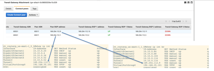
Also, notice that the tunnel1 source is Gig2 of CSR and the tunnel destination is the AWS TGW GRE IP


You will also notice that BGP peering information from CSRs match up between Azure UI and CSRs


On cAPIC you can also verify that you only have 1 TGW as shown in the figure below


Conclusion:
- cAPIC now supports AWS TGW Connect Attachment Type in Infra VPC. The CSRs are considered as the NVA (Network Virtualization Appliance) and BGP peering is built from CSRs to the TGW for control plane (over GRE tunnels). This gives you the benefit not having to deploy 2 TGWs per region. TGW is a highly available AWS resource and now you only need to use 1 TGW per region thus cutting down on your AWS resource consumption.
- If Tenant Region is not the infra region and is not a hub region (meaning no CSRs were deployed in that region), then from that Tenant Region connectivity to other DC sites (on Premise or Cloud) can still take place over the high speed TGW Inter Region Peering and then through the Infra CSRs. Pror to 5.2, you would either need to bring up CSRs in that non Infra HUB region or have to configure VGW tunnels between that Tenant VPC and the Infra VPC.